Chapter 1
Introduction
RUGGEDCOM RSG2100
Installation Guide
2 Description
Universal Power Supply Options
• Fully integrated, dual-redundant (optional) power supplies
• Universal high-voltage range: 88-300 VDC or 85-264 VAC
• Screw or pluggable terminal blocks for reliable, maintenance-free connections
• CSA/UL 60950-1 safety approved to 85 °C (185 °F)
Section1.2
Description
The RUGGEDCOM RSG2100 features various ports, controls and indicator LEDs on the display panel for
connecting, configuring and troubleshooting the device. The display panel can be located on the rear, front or top
of the device, depending on the mounting configuration.
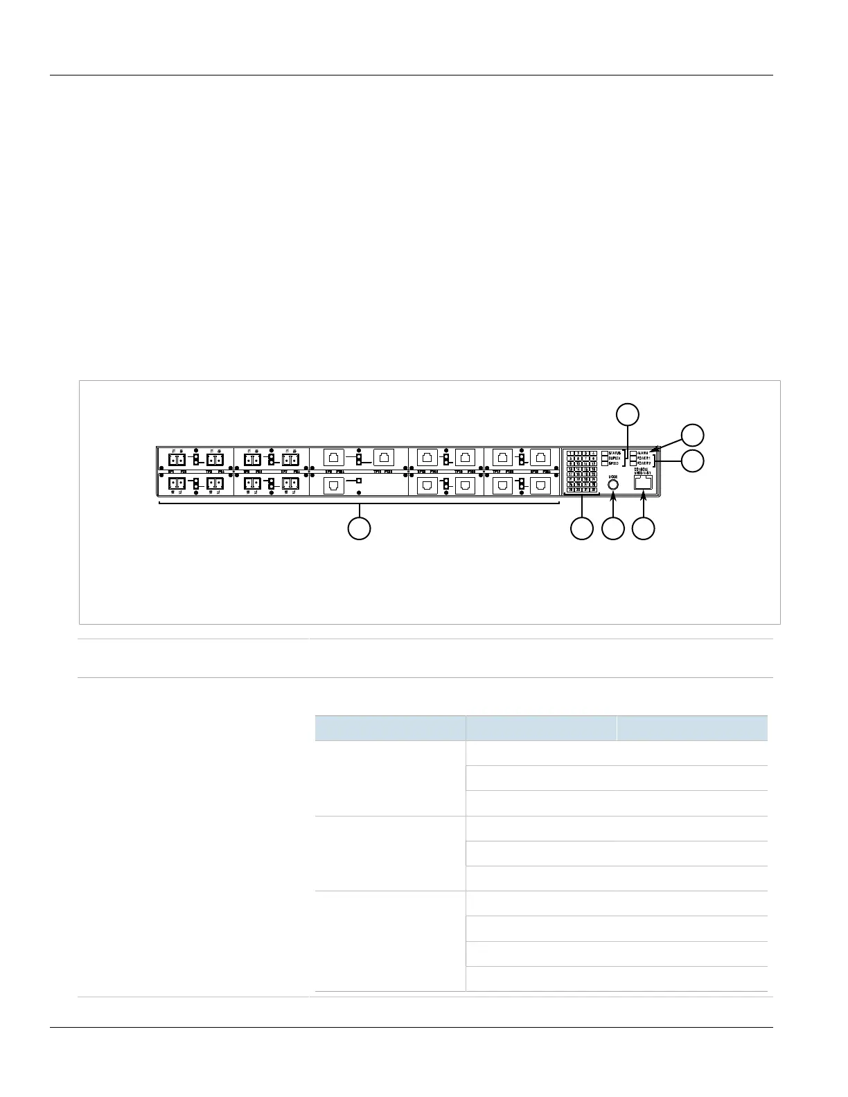
Figure1: RUGGEDCOM RSG2100
1.Fiber or Copper Ethernet Ports 2.Port Status Indicator LEDs 3.Mode Button 4.RS-232 Serial Console Port (RJ45) 5.Display Mode
Indicator LEDs 6.Alarm Indicator LED 7.Power Module Indicator LEDs
Communication Ports Ports for communicating with other devices or accessing the RUGGEDCOM ROS operating
system are described in Chapter3, Communication Ports.
Port Status Indicator LEDs Port status indicator LEDs indicate the operational status of each port, dependent on the
currently selected mode.
Mode Color/State Description
Green (Solid) Link detected
Green (Blinking) Link activity
Status
Off No link detected
Green Full duplex mode
Orange Half duplex mode
Duplex
Off No link detected
Green (Solid) 100 Mbps
Green (Blinking) 1000 Mbps
Orange (Solid) 10 Mbps
Speed
Off No link detected
 Loading...