RUGGEDCOM RX1501
Installation Guide
Chapter 2
Installing the Device
Connecting Power 11
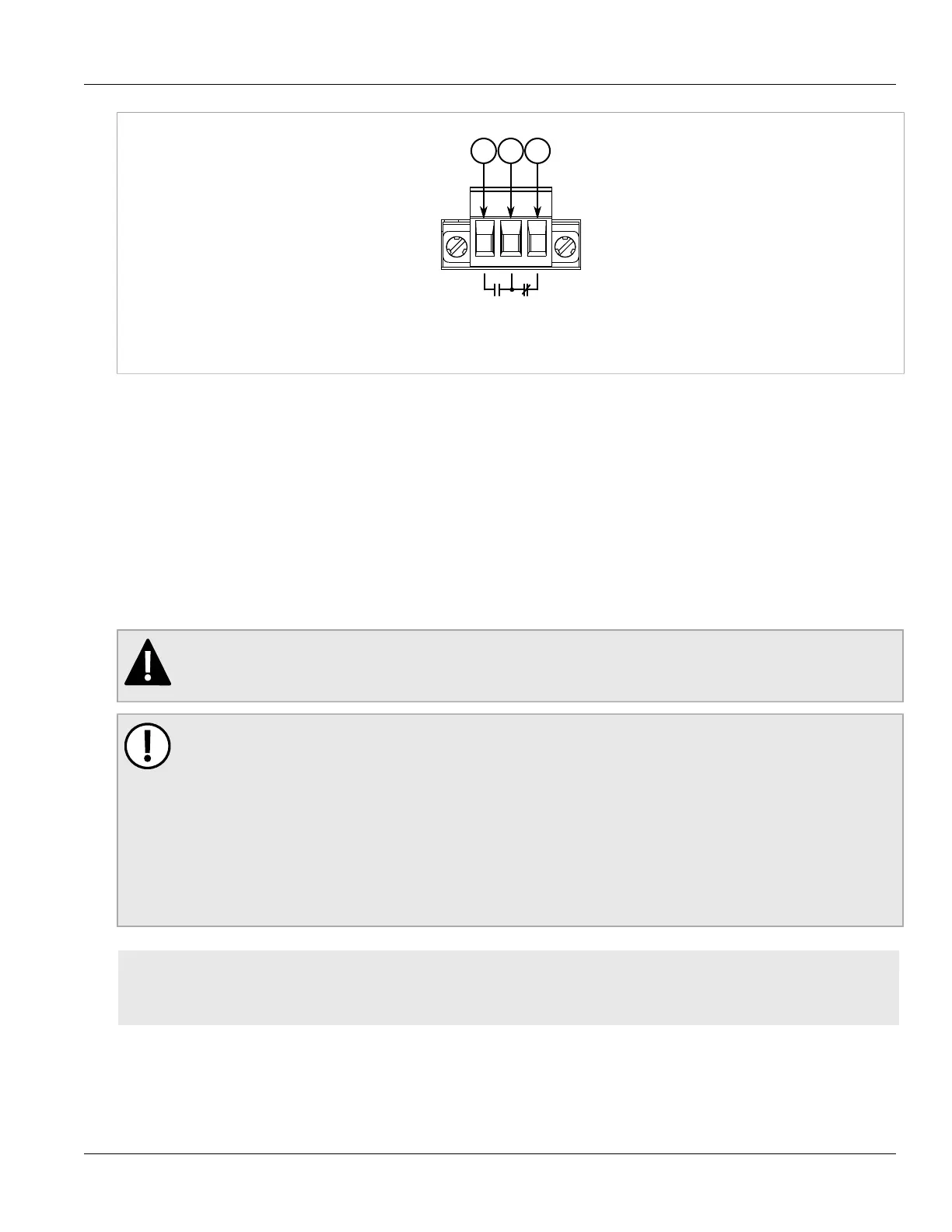
Figure5:Failsafe Alarm Relay Wiring
1.Normally Open 2.Common 3.Normally Closed
Section2.5
Connecting Power
The RUGGEDCOM RX1501 supports a single high AC, high DC or low DC power module.
Power modules can be equipped with either a screw or European-style (Euroblock) terminal block. The screw
terminal block is installed using Phillips screws and compression plates, allowing either bare wire connections or
crimped terminal lugs. Use #6 size ring lugs for secure, reliable connections under severe shock or vibration.
For information about installing or removing a power module, refer to Section4.3, “Installing/Removing Power
Modules”.
DANGER!
Electrocution hazard – risk of serious personal injury or death. Make sure the power source is off before
servicing the power module terminal.
IMPORTANT!
• Use minimum #16 gage copper wiring when connecting terminal blocks.
• The maximum wire length between the terminal block and power source must not exceed 6 m (20 ft)
for 24 V power supplies or 18 m (60 ft) for 48 V power supplies.
• For 125/230 VAC rated equipment, an appropriately rated AC circuit breaker must be installed.
• For 125/250 VDC rated equipment, an appropriately rated DC circuit breaker must be installed.
• It is recommended to provide a separate 20 A circuit breaker for each power module module.
• Equipment must be installed according to applicable local wiring codes and standards.
CONTENTS
• Section2.5.1, “Connecting High AC/DC Power”
• Section2.5.2, “Connecting Low DC Power”
 Loading...