Overview
1.13 Commissioning the HMI device
Basic Panels
24 Operating Instructions, 04/2012, A5E02421799-03
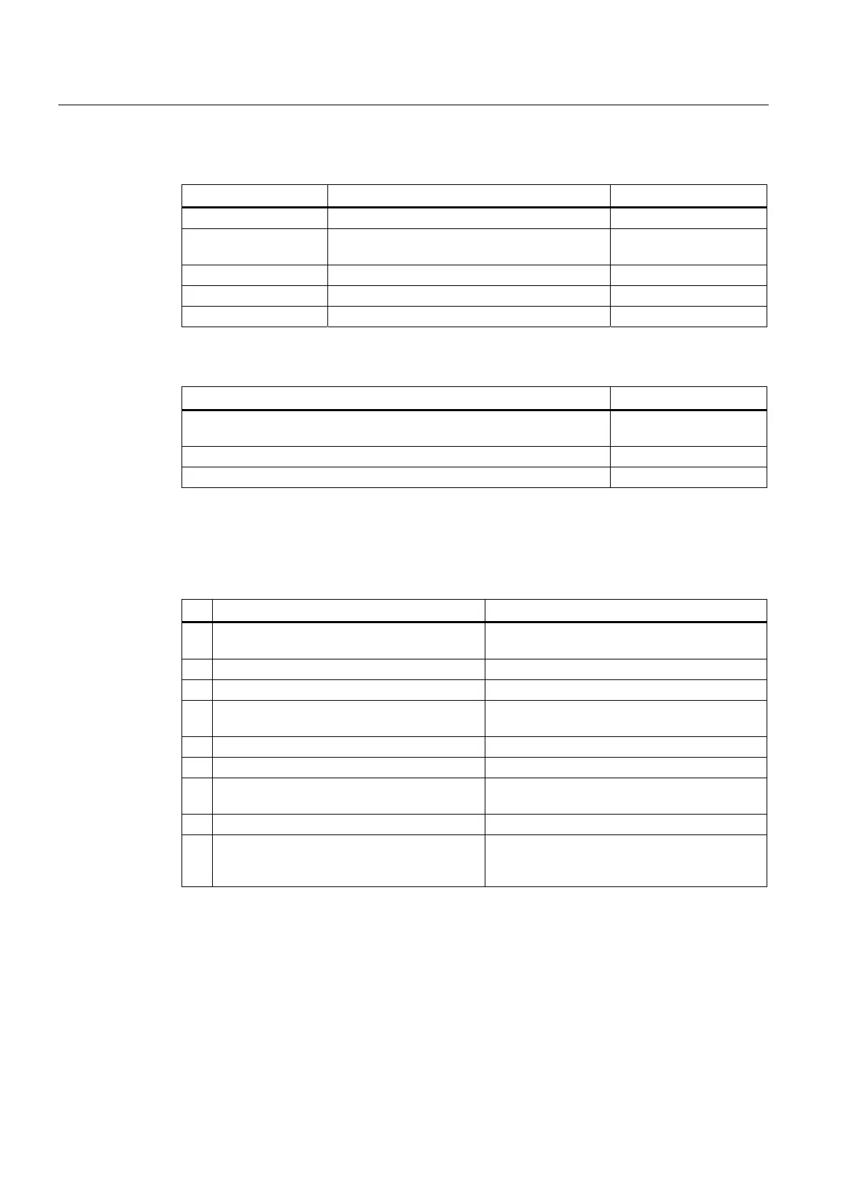
Protective foil
Name Purpose Order no.
Protective foil 4" Protective foil set for KTP400 Basic mono PN 6AV6 671-2EC00-0AX0
Protective foil 4"
widescreen
Protective foil set for KTP400 Basic color PN 6AV2124-6DJ00-0AX0
Protective foil 6" Protective foil set for KTP600 Basic 6AV6 671-2XC00-0AX0
Protective foil 10" Protective foil set for KTP1000 Basic 6AV6 671-3DC00-0AX5
Protective foil 15" Protective foil set for TP1500 Basic color PN 6AV6 574-1AD00-4EX0
Service packages
Purpose Order no.
Set with 20 plastic clamps for KP300 Basic Mono PN, KP400 Basic color
PN and KTP400 Basic color PN
6AV6671-8KX00-0AX2
Set with 20 aluminum mounting clamps for Basic Panels from 4" 6AV6671-8XK00-0AX0
Set of 10 power supply terminals 6AV6671-8XA00-0AX0
1.13 Commissioning the HMI device
This section contains an overview of the tasks required for commissioning the HMI device.
Description Section
1. Familiarize yourself with the safety
instructions.
Safety instructions (Page 25)
2. Prepare the HMI device for mounting. Preparations (Page 29)
3. Install the HMI device. Mounting the HMI device (Page 34)
4. Connect the equipotential bonding. Connecting the equipotential bonding circuit
(Page 38)
5. Connect the power supply. Connecting the power supply (Page 39)
6. Connect a configuration PC. Connecting the configuration PC (Page 42)
7. Enable sharing for data channel on the HMI
device.
Enabling a data channel (Page 76)
8. Transfer a project. Starting manual transfer (Page 91)
9. After transferring the project, disconnect the
HMI device from the configuration PC and
connect the HMI device to the PLC.
Connecting the PLC (Page 45)
 Loading...