Assignment of the terminal block
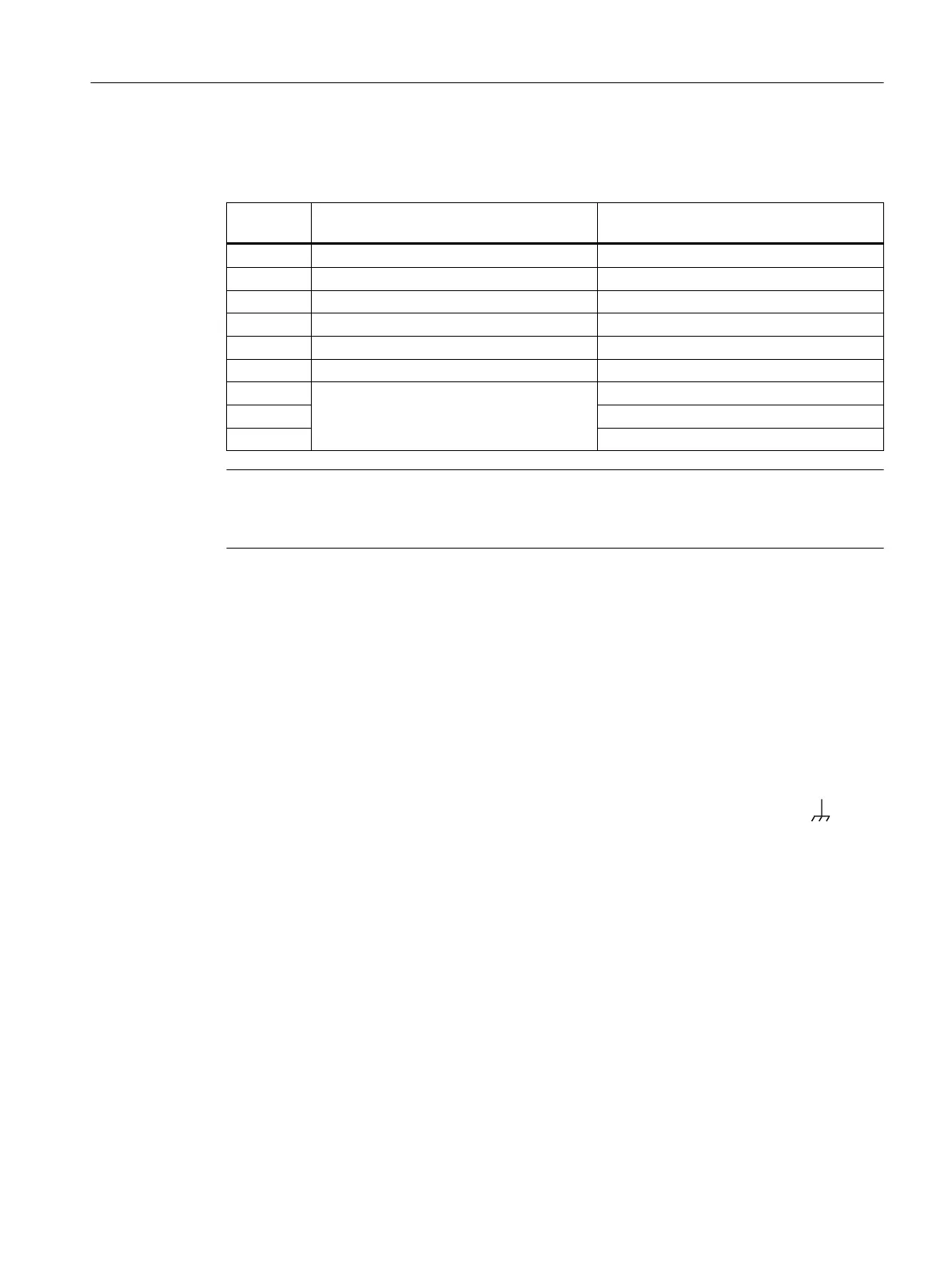
The connecting cable has the following assignment:
Contact Pin assignment of the RJ-11 plug Pin assignment of the D-sub female con‐
nector
1 - -
2 - TD (Transmit Data)
3 TD (Transmit Data) RD (Receive Data)
4 SG (Signal Ground) -
5 RD (Receive Data) SG (Signal Ground)
6 - -
7 -
8 -
9 -
Note
Pin assignment of the RJ-11 jack on the device
The RJ-11 jack on the device has a pinout to match the RJ-11 plug of the connecting cable.
5.6 Functional ground
EMC disturbances are diverted to ground via the functional ground. This ensures the immunity
of the data transmission.
The functional ground must be implemented with low impedance. The connection of the
functional ground must be established directly on the mounting plate or the DIN rail terminal.
The IE switch has a grounding screw (fillister head screw with clamping washer und disk) for
functional ground, refer to the section "Device views (Page 21)".
The grounding screw is identified by the following symbol for the functional ground .
Follow the steps below to connect the functional ground:
1. Loosen the grounding screw).
2. Put the grounding terminal and grounding screw together.
3. Tighten the grounding screw with a maximum torque of 0.75 Nm.
Protective/functional ground
The connection of the reference potential surface with the protective ground system is normally
in the cabinet close to the power feed-in. This ground conducts fault currents to ground safely
and according DIN/VDE 0100 is a protective ground to protect people, animals and property
from too high contact voltages.
Apart from the protective ground, there is functional grounding in the cabinet. According to
EN60204-1 (DIN/VDE 0113 T1) electrical circuits must be grounded. The chassis (0 V) is
Connecting up
5.6 Functional ground
SCALANCE XC-200
Operating Instructions, 12/2017, C79000-G8976-C442-03 55
 Loading...