4.7 LED display
4.7.1 Overview
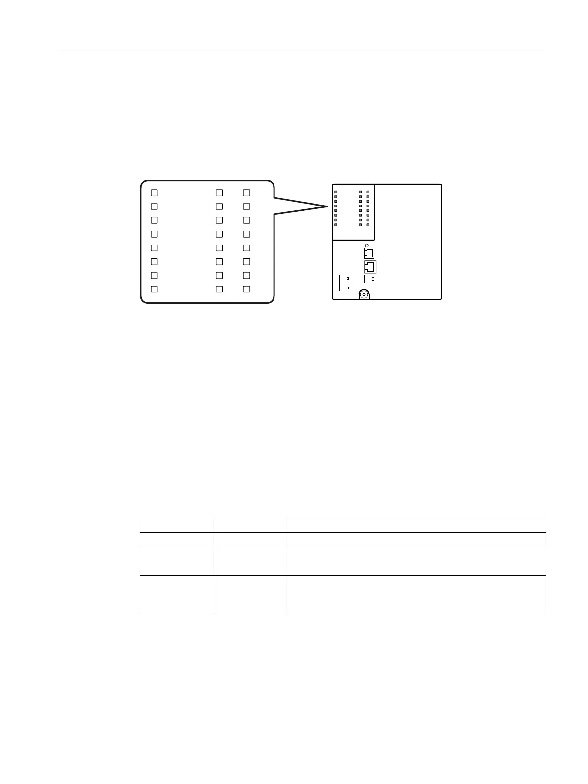
The following gure shows the arrangement of the LEDs.
)
50
6%
'0
/
3
&20%2
3
3
3
3
3
3
3
/
'0
F LED for displaying the fault/error status
RM LED for displaying the "redundancy manager" function
SB LED for display of redundantly linked rings
DM1/DM2 LEDs for displaying the display mode
L1/L2 LEDs for displaying the power supply
P LEDs for displaying the port status *)
COMBO Indicates that the LEDs belong to combo ports
*
)
The number of port LEDs depends on the device.
4.7.2 "RM" LED
The "RM" LED indicates whether or not the device is a redundancy manager and whether or not
the ring is operating free of error.
LED color LED status Meaning
- O The device is not a redundancy manager.
Green On The device is a redundancy manager.
The ring is working without problems, monitoring is activated.
Green Flashing The device is a redundancy manager.
An interruption has been detected on the ring and the device has
switched through.
Description of the device
4.7 LED display
SCALANCE XM-400
Operating Instructions, 03/2021, C79000-G8976-C306-10 33
 Loading...