4.7.3 "SB" LED
With a redundant linking of rings, the "SB" LED shows the status of the redundant connection.
The available options of a redundant link are as follows:
• Standby Function
• MRP Interconnection
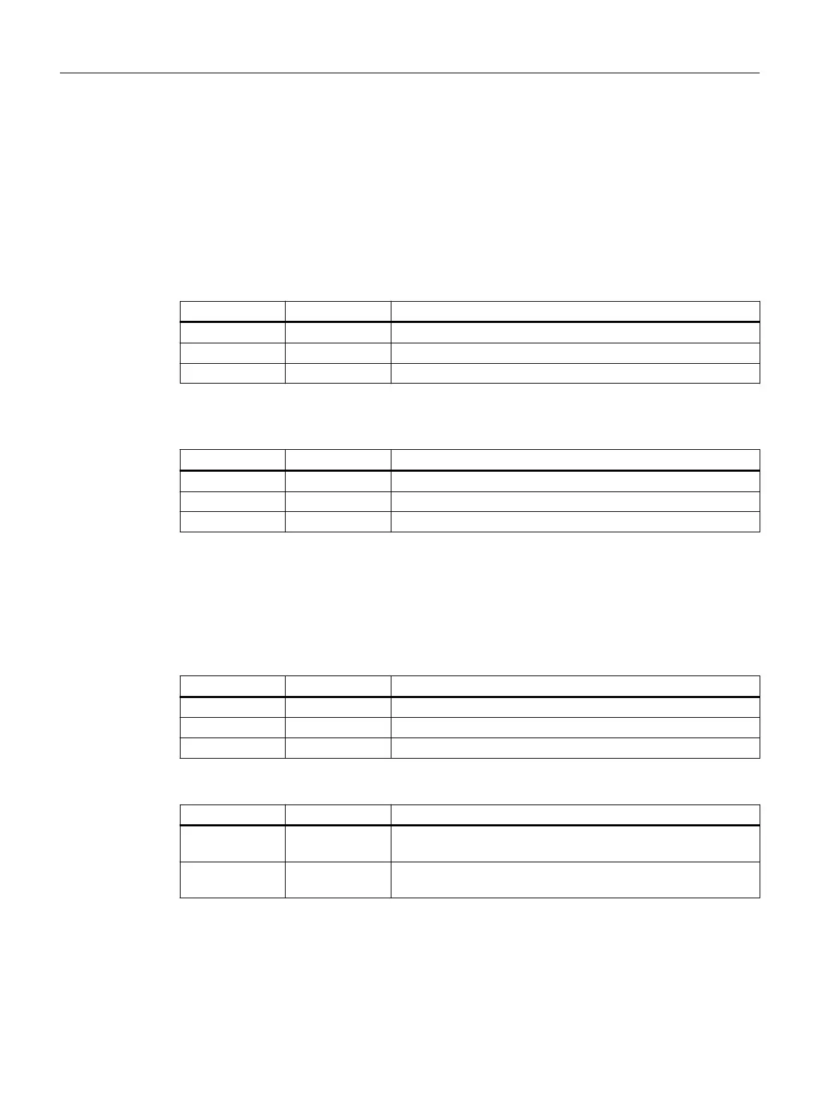
Standby Function
LED color LED status Meaning
- O The standby function is disabled.
Green On The standby function is enabled. The standby section is passive.
Green Flashing The standby function is enabled. The standby section is active.
MRP Interconnection
LED color LED status Meaning
- O MRP Interconnection is disabled.
Green On MRP Interconnection redundancy is available.
Green Flashing MRP Interconnection redundancy is not available.
4.7.4 "F" LED
The "F" LED shows the fault/error status of the device.
Meaning during device startup
LED color LED status Meaning during device startup
- O Device startup was completed successfully.
Red On Device startup is not yet completed or errors have occurred.
Red Flashing There are errors in the rmware.
Meaning during operation
LED color LED status Meaning during operation
- O The device is operating free of errors. The signaling contact is
closed.
Red On The device has detected a problem. The signaling contact has
opened.
4.7.5 LEDs "DM1" and "DM2"
The "DM1" and "DM2" LEDs indicate which display mode is set.
Description of the device
4.7 LED display
SCALANCE XM-400
34 Operating Instructions, 03/2021, C79000-G8976-C306-10
 Loading...