Electrical connection
6.1 Connecting the machine
1MB..1/2/3/4 - shaft heights 63 ... 355
76 Operating Instructions, 06/2020, A5E44455710A
6.1.1.10 Minimum air clearances
After proper installation, verify that the minimum air clearances between non-insulated parts
are maintained. Be aware of any protruding wire ends.
Table 6- 2 Minimum air clearance dependent on rms value of the alternating voltage
U
rms
Rms value of the alternating
voltage
U
rms
Values apply at an installation altitude of up to 2000
m.
When determining the required minimum air clearance, the voltage value in the table may be in-
creased by a factor of 1.1, so that the rated input voltage range is taken into account during gen-
6.1.1.11 Internal equipotential bonding
The internal equipotential bonding between the grounding terminal in the terminal box, the
terminal box components and the machine enclosure is ensured via metallic contact, a
copper braided strip or a stranded wire.
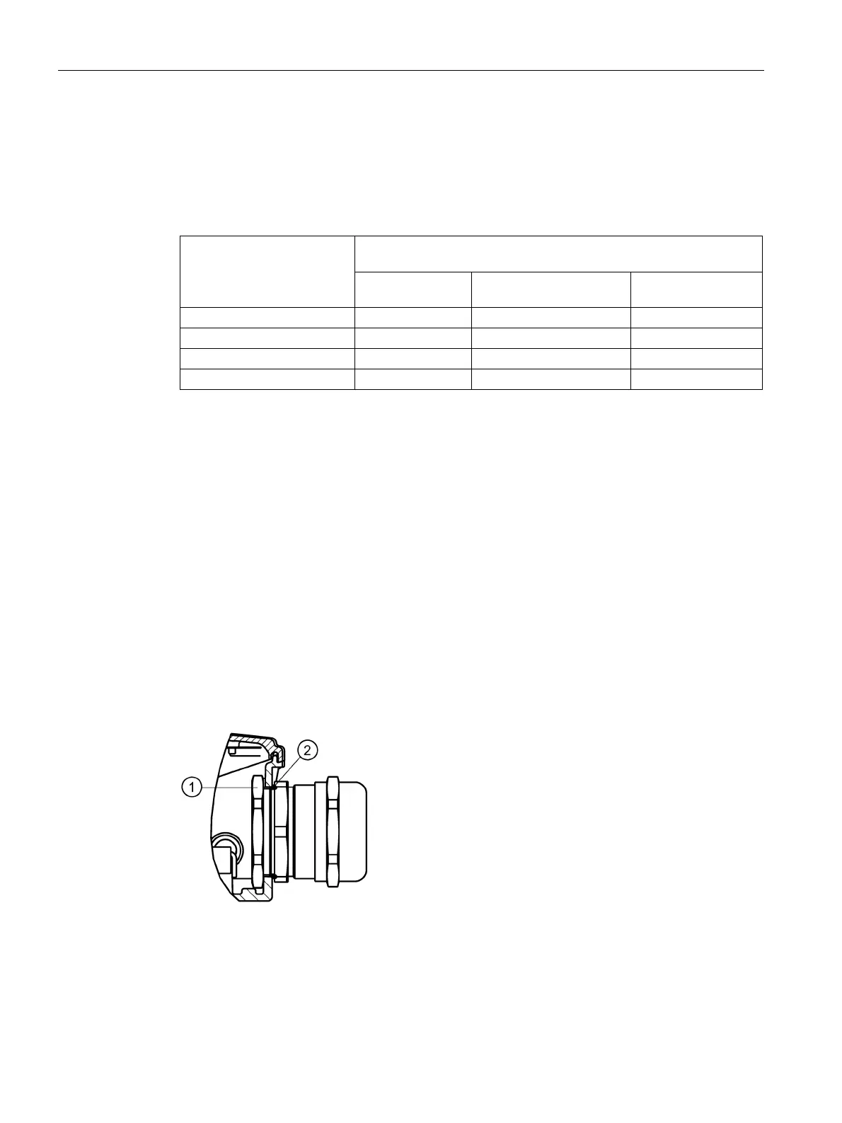
6.1.2 Cable glands
Cable glands with (sheet metal) nuts (EN 50262)
 Loading...


