EasyManua.ls Logo

Siemens SINEC L2 User Manual

Siemens SINEC L2
224 pages
To Next Page IconTo Next Page
To Previous Page IconTo Previous Page
Page #105 background imageLoading...
Page #105 background image
S5-95U, SINEC L2 Integral Standard Function Blocks L2-SEND and L2-RECEIVE
5.3 Parameter Assignment Error Byte (PAFE)
The parameter assignment error byte (PAFE) indicates errors made when assigning parameters
for L2-SEND and L2-RECEIVE. Flag byte 255 is reserved as the parameter assignment error byte.
You can scan the PAFE in the control program and program the reactions to errors that occur.
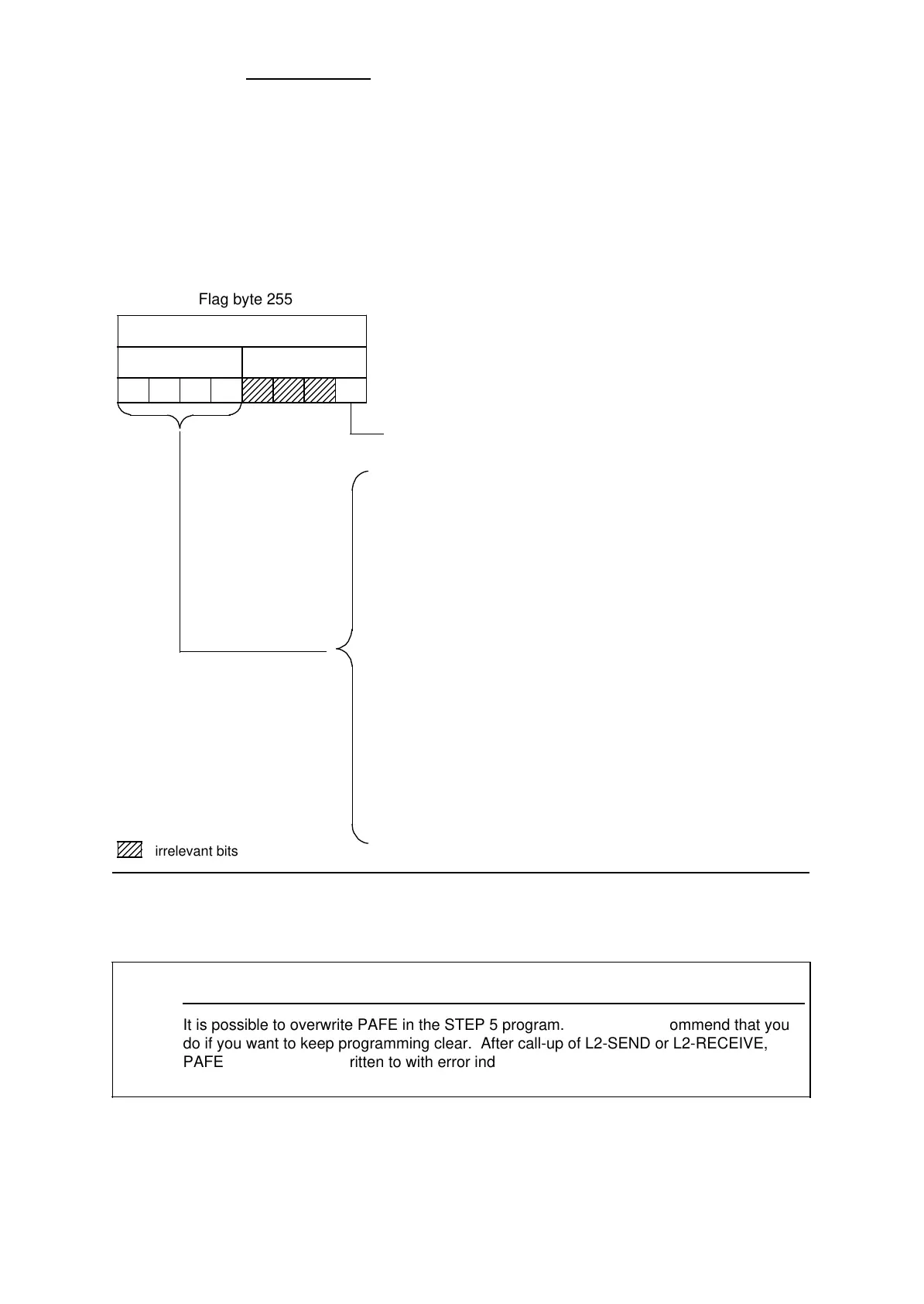
Figure 5-2. Structure of the PAFE Parameter Assignment Error Byte
0: - No parameter assignment error
1: - Parameter assignment error
0 - Irrelevant
1 - Irrelevant
2 - Area does not exist (DB does not exist / is not
permitted)
3 - Area is too small
4 - Overload, access to L2 interface is not possible
5 - Incorrect contents of status byte (user access to the
status byte is not permitted)
6 - Source or destination parameters not permitted for
L2-SEND/L2-RECEIVE
7 - Irrelevant
8 - Irrelevant
9 - Irrelevant
A - Irrelevant
B - Parameter assignment error (length incorrect)
C - Destination address = source address
D - Programmable controller is a passive station, job is
not possible
E - No parameters assigned for the job
F - Job number not permissible
7654 3210
Error codes
a
a
a
a
a
a
a
a
a
a
a
a
a
a
a
a
a
a
a
a
a
a
a
a
a
a
a
a
a
a
a
a
a
a
a
a
a
a
a
a
a
a
a
a
a
a
a
a
a
a
a
a
a
a
a
a
a
a
a
a
a
a
a
a
a
a
a
a
a
a
a
a
a
a
a
a
a
a
a
a
a
a
a
a
a
Flag byte 255
a
a
a
a
a
a
a
a
a
a
a
a
a
a
a
a
a
a
a
a
a
a
a
a
a
a
a
a
a
a
a
a
a
a
a
a
a
a
a
a
a
a
a
a
a
a
a
a
a
a
a
a
a
a
a
a
a
a
a
a
a
a
a
a
a
a
a
a
a
a
a
a
a
a
a
a
a
a
a
a
a
a
a
a
a
a
a
a
a
a
a
a
a
a
a
a
a
a
a
a
a
a
irrelevant bits
a
a
a
a
a
a
a
a
a
a
a
a
a
a
a
a
a
a
a
a
a
a
a
a
It is possible to overwrite PAFE in the STEP 5 program. We do not recommend that you
do if you want to keep programming clear. After call-up of L2-SEND or L2-RECEIVE,
PAFE may have been written to with error indications so you need to scan it in the STEP
5 program.
Note
EWA 4NEB 812 6112-02
5-5

Table of Contents

Question and Answer IconNeed help?

Do you have a question about the Siemens SINEC L2 and is the answer not in the manual?

Siemens SINEC L2 Specifications

General IconGeneral
Power Supply24 V DC
Operating Temperature-40 to +70 °C
Product FamilySINEC
Protection ClassIP30
Product TypeSwitch
DimensionsVaries depending on the specific model
Network StandardsIEEE 802.3, IEEE 802.1Q, IEEE 802.1p

Summary

1 System Description

1.4 Assigning Parameters for the L2 Interface of the S5-95U

Details parameter assignment in DB1 for the L2 interface, including basic parameters and data transmission parameters.

2 Installation Guidelines

2.1 Basic Configuration

Illustrates main components of SINEC L2 in RS 485 and S5-95U installation technology.

2.2 Installing a SINEC L2 Bus Segment

Explains how to install a SINEC L2 bus segment, including mounting the bus cable on the connector.

3 Start-Up, Tests, and Diagnostics

3.2 START-UP Sequence

Details the sequence of operations during startup, including power recovery and cold restart routines.

3.3 Starting Up a System

Provides safety suggestions, minimum hardware requirements, and startup diagnostics procedures.

4 Data Transmission Using a Standard Connection

4.2 Assigning Parameters in DB1 of the S5-95U for Data Exchange with Standard Connections

Details parameter assignment in DB1 for standard connections, including mailbox and coordination byte locations.

5 Integral Standard Function Blocks L2-SEND and L2-RECEIVE

5.1 Parameters for L2-SEND and L2-RECEIVE

Lists and explains parameters for L2-SEND/L2-RECEIVE, including job number allocation and data source/destination.

6 Data Transmission Using PLC-to-PLC Connections

6.2 Assigning Parameters in DB1 of the S5-95U for Data Exchange with PLC-to-PLC Connections

Details parameter assignment in DB1 for PLC-to-PLC connections, including station identification and status byte locations.

7 Data Transmission Using Cyclic I/O

7.2 Assigning Parameters in DB1 of the S5-95U for Data Exchange with Cyclic I/O

Covers parameter assignment in DB1 for cyclic I/O, including ZP areas, status bytes, and ZP master/slave connection.

8 Data Transmission by Accessing Layer 2 Services

8.3 Assigning the S5-95U Parameters for Data Communications

Details parameter assignment in DB1 for layer 2 accesses, including status byte locations and job number definitions.

9 Programmer Functions Over the SINEC L2 Network

9.2 Selecting the L2 Interface

Guides on selecting the SINEC L2 interface using the programmer's 'INTERFACE SELECTION' function.

9.4 Editing a Path

Details how to edit a path to reach a station on the SINEC L2 LAN using the 'BUS DIALLING' utility.

9.5 Setting the L2 Basic Parameters on the Programmer

Describes how to set L2 basic parameters on the programmer via the 'SYSID CP L2 (LOCAL)' screen.

Related product manuals