EasyManua.ls Logo

Siemens SINEC L2 User Manual

Siemens SINEC L2
224 pages
To Next Page IconTo Next Page
To Previous Page IconTo Previous Page
Page #93 background imageLoading...
Page #93 background image
S5-95U, SINEC L2 Data Transmission Using a Standard Connection
4.5 Programming Example for Data Transmission via a Standard
Connection
This section explains the structure of the control program in the following example:
Programmable controller 1 is to receive data from programmable controller 2 and to transmit data to
programmable controller 2. Refer to section 4.1 for the description of the hardware configuration.
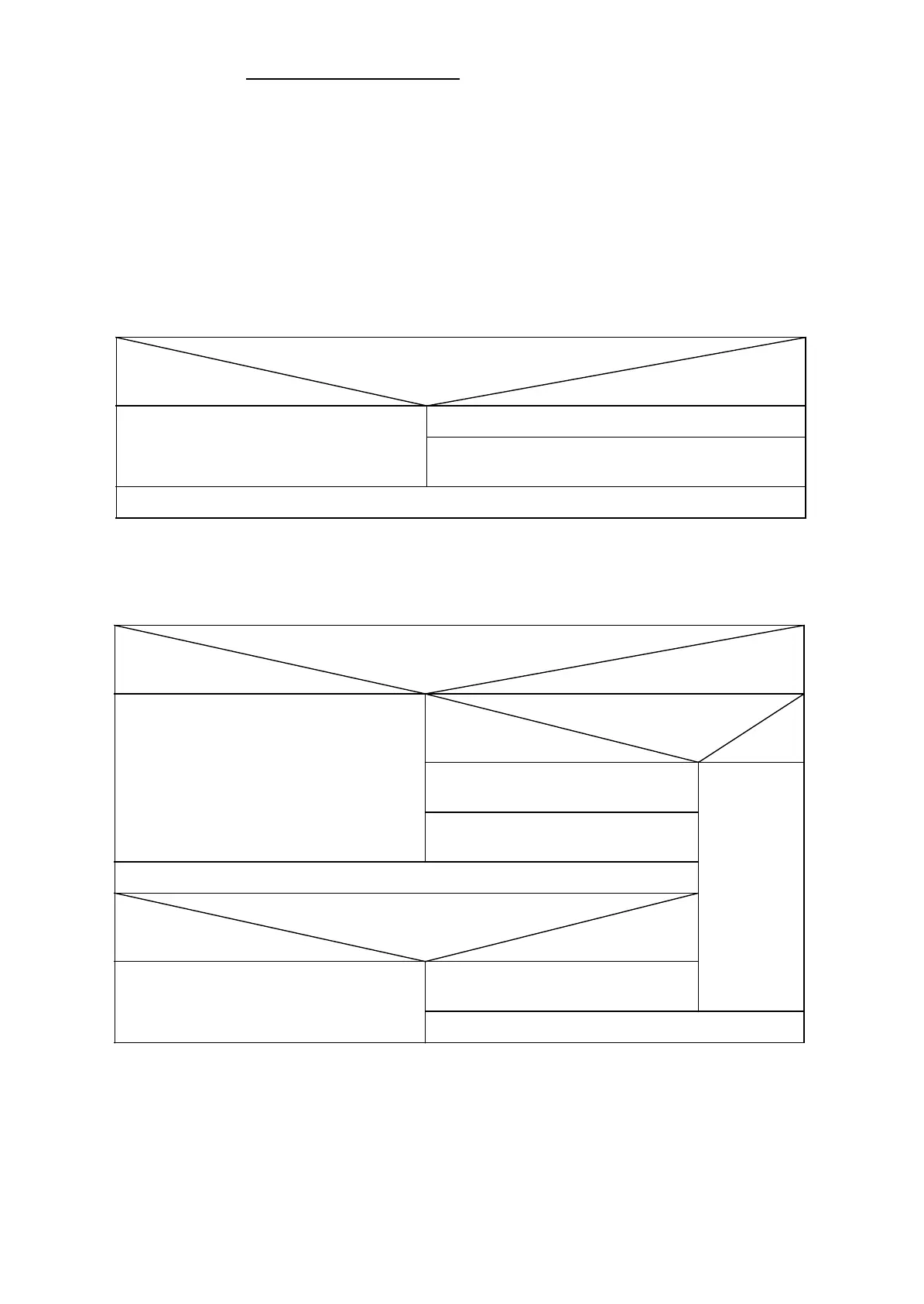
The control program in FB1 for receiving data is structured as illustrated below.
Is the receive mailbox enabled to receive? (Bit 7 of CBR=1?)
yes no
Waiting for data arrival
(Bit 7 of CBR=0)
Evaluation of the receive mailbox
Receive mailbox enabled to receive again (Bit 7 of CBR=1)
Jump to program section “transmit”
The control program in FB1 for transmitting data is structured as illustrated below.
Is the send mailbox enabled to transmit? (bit 7 of CBS=1?)
yes no
Data transmission (PLC transmits)
Write transmit data, data length and
address of receiver to the send mailbox
Enable send mailbox to transmit
(set bit 7 of CBS to 1)
Acknowledge last transmission
(reset transmit trigger bit )
Is there an error indication in CBS?
yes no
Transmit job still pending
(transmit trigger bit is not reset)
End
Is the transmit job running? (transmit
trigger bit =1?)
yes no
EWA 4NEB 812 6112-02
4-9

Table of Contents

Question and Answer IconNeed help?

Do you have a question about the Siemens SINEC L2 and is the answer not in the manual?

Siemens SINEC L2 Specifications

General IconGeneral
Power Supply24 V DC
Operating Temperature-40 to +70 °C
Product FamilySINEC
Protection ClassIP30
Product TypeSwitch
DimensionsVaries depending on the specific model
Network StandardsIEEE 802.3, IEEE 802.1Q, IEEE 802.1p

Summary

1 System Description

1.4 Assigning Parameters for the L2 Interface of the S5-95U

Details parameter assignment in DB1 for the L2 interface, including basic parameters and data transmission parameters.

2 Installation Guidelines

2.1 Basic Configuration

Illustrates main components of SINEC L2 in RS 485 and S5-95U installation technology.

2.2 Installing a SINEC L2 Bus Segment

Explains how to install a SINEC L2 bus segment, including mounting the bus cable on the connector.

3 Start-Up, Tests, and Diagnostics

3.2 START-UP Sequence

Details the sequence of operations during startup, including power recovery and cold restart routines.

3.3 Starting Up a System

Provides safety suggestions, minimum hardware requirements, and startup diagnostics procedures.

4 Data Transmission Using a Standard Connection

4.2 Assigning Parameters in DB1 of the S5-95U for Data Exchange with Standard Connections

Details parameter assignment in DB1 for standard connections, including mailbox and coordination byte locations.

5 Integral Standard Function Blocks L2-SEND and L2-RECEIVE

5.1 Parameters for L2-SEND and L2-RECEIVE

Lists and explains parameters for L2-SEND/L2-RECEIVE, including job number allocation and data source/destination.

6 Data Transmission Using PLC-to-PLC Connections

6.2 Assigning Parameters in DB1 of the S5-95U for Data Exchange with PLC-to-PLC Connections

Details parameter assignment in DB1 for PLC-to-PLC connections, including station identification and status byte locations.

7 Data Transmission Using Cyclic I/O

7.2 Assigning Parameters in DB1 of the S5-95U for Data Exchange with Cyclic I/O

Covers parameter assignment in DB1 for cyclic I/O, including ZP areas, status bytes, and ZP master/slave connection.

8 Data Transmission by Accessing Layer 2 Services

8.3 Assigning the S5-95U Parameters for Data Communications

Details parameter assignment in DB1 for layer 2 accesses, including status byte locations and job number definitions.

9 Programmer Functions Over the SINEC L2 Network

9.2 Selecting the L2 Interface

Guides on selecting the SINEC L2 interface using the programmer's 'INTERFACE SELECTION' function.

9.4 Editing a Path

Details how to edit a path to reach a station on the SINEC L2 LAN using the 'BUS DIALLING' utility.

9.5 Setting the L2 Basic Parameters on the Programmer

Describes how to set L2 basic parameters on the programmer via the 'SYSID CP L2 (LOCAL)' screen.

Related product manuals