Data Transmission Using a Standard Connection S5-95U, SINEC L2
Structure of the Send Coordination Byte (CBS)
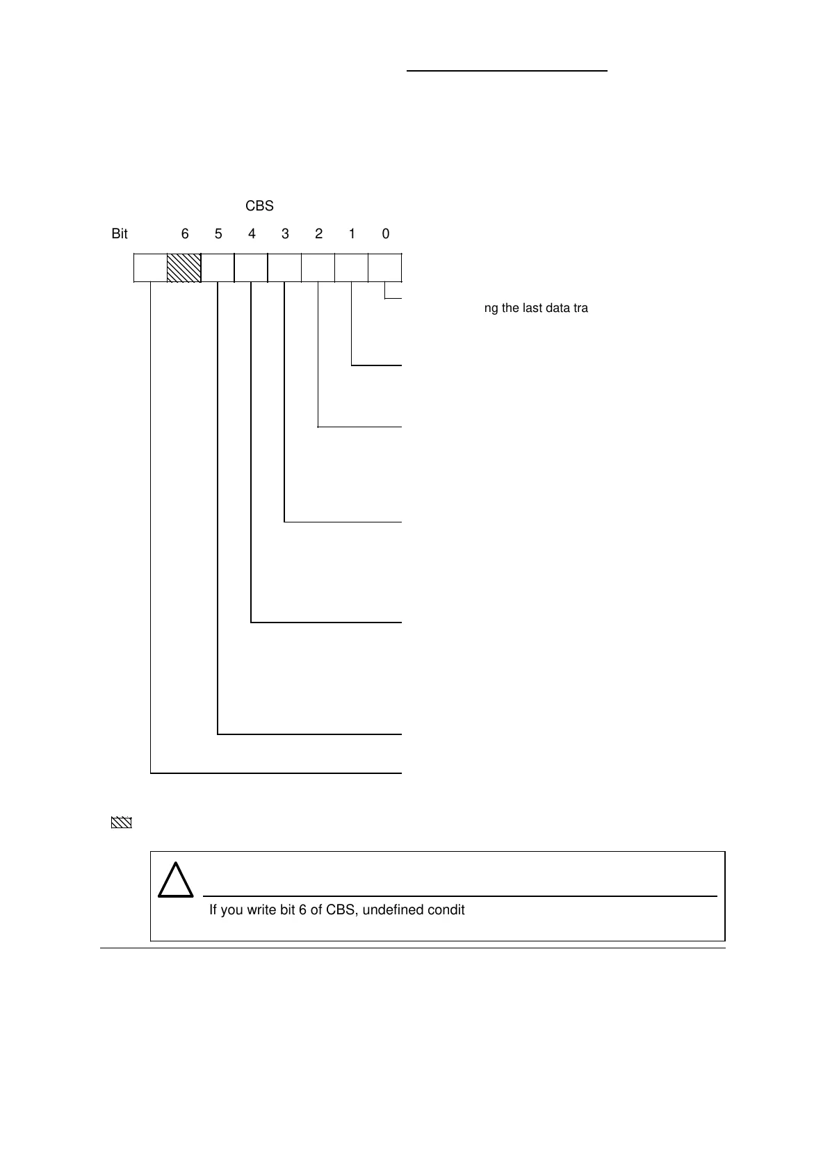
Figure 4-5 shows the structure of the send coordination byte (CBS).
Figure 4-5. Structure of the Send Coordination Byte (CBS) for a Standard Connection
R R RRR RW/R
7
a
a
a
a
a
a
a
a
a
a
a
a
a
a
a
a
a
a
a
a
a
a
a
a
a
a
a
a
a
a
6 5 4 3 2 1 0
CBS
Bit
If you write bit 6 of CBS, undefined conditions can occur in the network.
Bit 6 is not available to the user.
Warning
!
R: Read only
W/R: Write / Read
Reserved bit
a
a
a
a
a
a
0: No error during the last data transmission
1: Error during the last data transmission
(Bits 1 to 5 describe the cause for an error in
more detail.)
0: The destination programmable controller
acknowledges correctly.
1: The destination programmable controller does not
acknowledge.
0: No error
1: Send mailbox error (either the DB is not available
or the send mailbox is too small), or
there is a parameter assignment error in the send
mailbox (either the “length of net data” or the “L2
destination address” is incorrect).
0: The destination PLC is in the RUN mode.
1: The destination PLC is in the STOP mode.
PLC STOP is recognized only if the destination
station is an S5-95U and if the connection has
been configured correctly. (It does not work with
broadcasting.)
0: No negative acknowledgment
1: Negative acknowledgment; either one of the
following:
- Receiver’s receive mailbox not empty
- Connection not configured on
- Bus error (hardware fault)
- Addressed station is passive
0: The L2 interface is not overloaded.
1: The L2 interface is overloaded.
0: The user program can process the send mailbox.
(The operating system has no access to the send
mailbox.)
1: The send mailbox is enabled to transmit. (The
user program has no access to the send mailbox.)
4-6
EWA 4NEB 812 6112-02
 Loading...