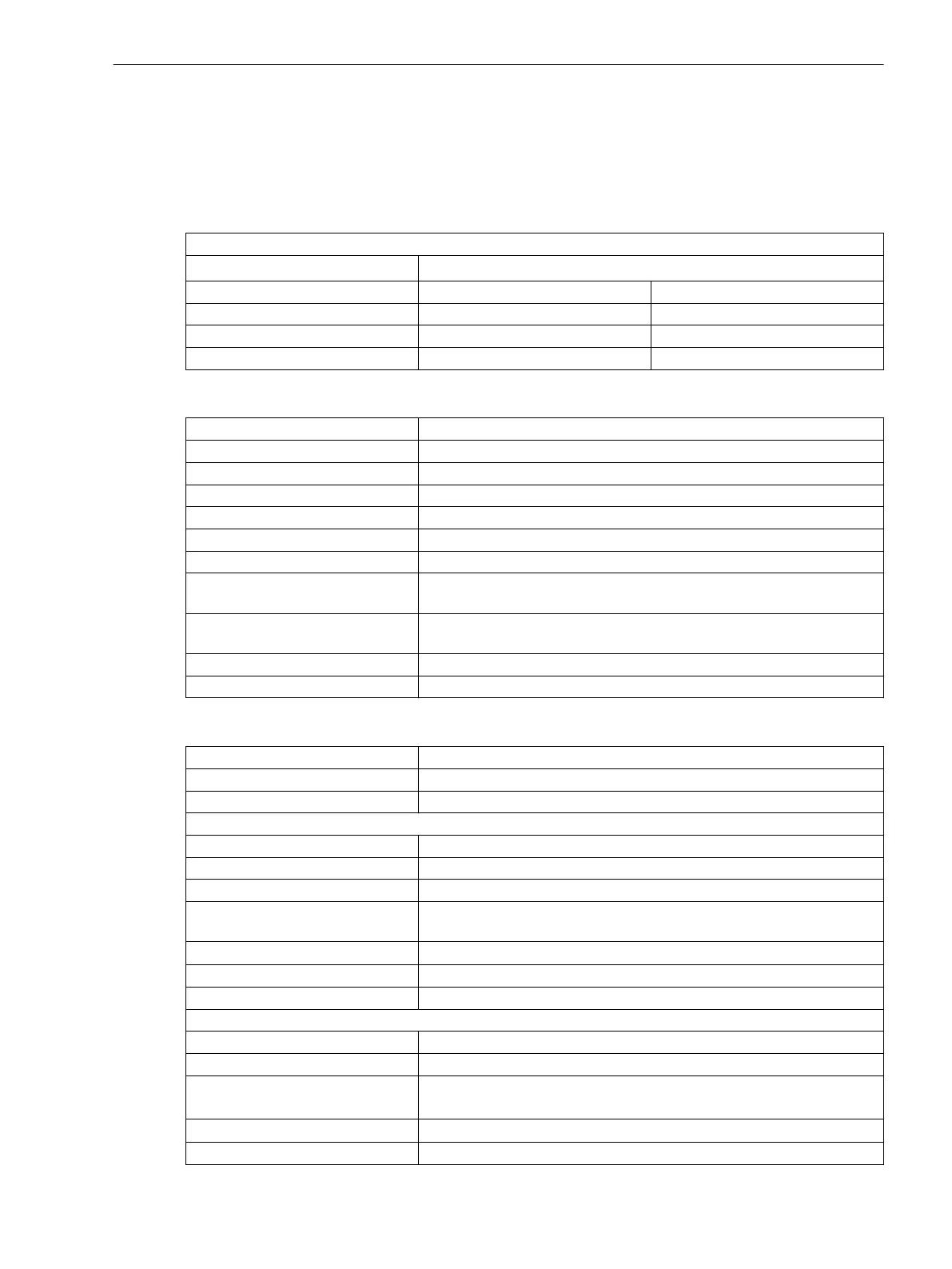
General Device Data
Analog Inputs
Voltage Input
All current, voltage, and power data are specified as RMS values.
Rated frequency f
rated
50 Hz, 60 Hz
Input and output modules IO202, IO208, IO211, IO214 IO215
Measuring range 0 V to 200 V 0 V to 7.07 V
Input impedance < 0.1 VA < 0.01 VA
Thermal rating 230 V continuously 20 V continuously
Measuring-Transducer Inputs (via Module ANAI-CA-4EL)
Insulation class SELV (Safety Extra Low Voltage) (according to IEC 60255-27)
Connector type 8-pin multiple contact strip
Differential current input channels 4
Measuring range DC -24 mA to +24 mA
Fault < 0.5 % of the measuring range
Input impedance 140 Ω
Conversion principle Delta-sigma (16 bit)
Permissible potential difference
between channels
DC 20 V
Galvanic separation from ground/
housing
DC 700 V
Permissible overload DC 100 mA continuously
Measurement repetition 200 ms
Measuring-Transducer Inputs (via Module ARC-CD-3FO)
Connector type
AVAGO AFBR-4526Z
Number of transceivers 3
Fiber type Polymer Optical Fiber (POF) 1 mm
Receiver
Maximum -10 dBm ± 2 dBm
Minimum -40 dBm ± 2 dBm
Spectrum 400 nm to 1100 nm
Attenuation In the case of plastic optical fibers, you can expect a path attenuation of
0.2 dB/m Additional attenuation comes from the plug and sensor head.
Optical budget
1
Minimal 25 dB
Analog sampling rate 16 kHz
ADC type 10-bit successive approximation
Transmitter
Type LED
Wavelength λ = 650 nm
Transmit power Minimum 0 dBm
Maximum 2 dBm
Numerical aperture
0.5
2
Signal rate connection test 1 pulse per second
11.1
11.1.1
Technical Data
11.1 General Device Data
SIPROTEC 5, High-Voltage Bay Controller, Manual 1105
C53000-G5040-C015-A, Edition 05.2018

 Loading...


