Directional Overcurrent Protection, Phases
Stage with Definite-Time Characteristic Curve
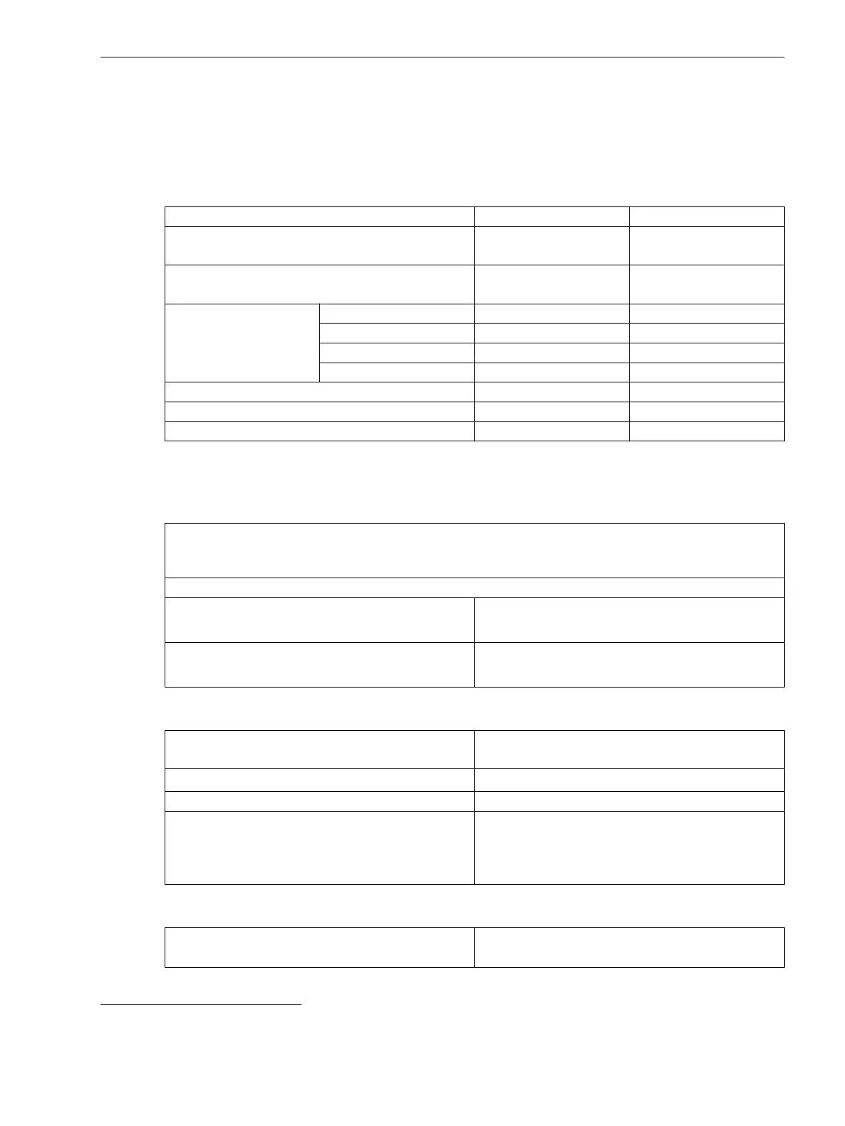
Setting Values
Rotation angle of the reference voltage -180° to +180° Increments of 1°
Directional mode Forward
Reverse
–
Method of measurement Fundamental component
RMS value
–
Threshold value
59
1 A @ 50 and 100 Irated 0.030 A to 35.000 A Increments of 0.001 A
5 A @ 50 and 100 Irated 0.15 A to 175.00 A Increments of 0.01 A
1 A @ 1.6 Irated 0.001 A to 1.600 A Increments of 0.001 A
5 A @ 1.6 Irated 0.005 A to 8.000 A Increments of 0.001 A
Dropout ratio 0.90 to 0.99 Increments of 0.01
Time delay 0.00 s to 60.00 s Increments of 0.01 s
Dropout delay 0.00 s to 60.00 s Increments of 0.01 s
Dropout
The greater dropout differential (= | pickup value – dropout value |) of the following 2 criteria
applies:
Dropout differential derived from the parameter
Dropout ratio
If this parameter is not available, a dropout ratio of 95 % applies for overcurrent and of 105 % for undercur-
rent functionality.
Minimum absolute dropout differential
Protection-class current transformer 15 mA sec. (I
rated
= 1 A) or
75 mA sec. (I
rated
= 5 A)
Instrument current transformer 0.5 mA sec. (I
rated
= 1 A) or
2.5 mA sec. (I
rated
= 5 A)
Direction Determination
Type
With healthy voltages
With voltage memory 2 s
Forward range V
ref,rot
±88°
Dropout differential forward/reverse range 1°
Directional sensitivity Unlimited for 1 and 2-phase short circuits
Dynamically unlimited, stationary for 3-phase short
circuits
Approx. 13 V phase-to-phase
Times
Operate time with time delay = 0 ms
Approx. 37 ms + OOT
60
at 50 Hz
Approx. 22 ms + OOT at 60 Hz
11.10
11.10.1
59
If you have selected the method of measurement = RMS value, do not set the threshold value under 0.1 l
rated,sec
.
60
OOT (Output Operating Time): additional delay of the output medium used, for example 5 ms with fast relays
Technical Data
11.10 Directional Overcurrent Protection, Phases
SIPROTEC 5, High-Voltage Bay Controller, Manual 1143
C53000-G5040-C015-A, Edition 05.2018

 Loading...


