Connection
8.4 Connection cross-sections
SIRIUS 3RU thermal overload relays / SIRIUS 3RB electronic overload relays
Manual, 09/2016, A5E03656507420A/RS-AB/003
103
Connection cross-sections
8.4.1
Conductor cross-sections for screw-type connection systems
Conductor cross-sections for screw-type connection systems
The tables below define the permissible conductor cross-sections for main terminals and
auxiliary conductor connections in sizes S00 to S10 / S12 for screw-type connection
systems.
Note
If two different conductor cross
-sections are connected to one clamping point, both cross-
sections must be located in the range specified.
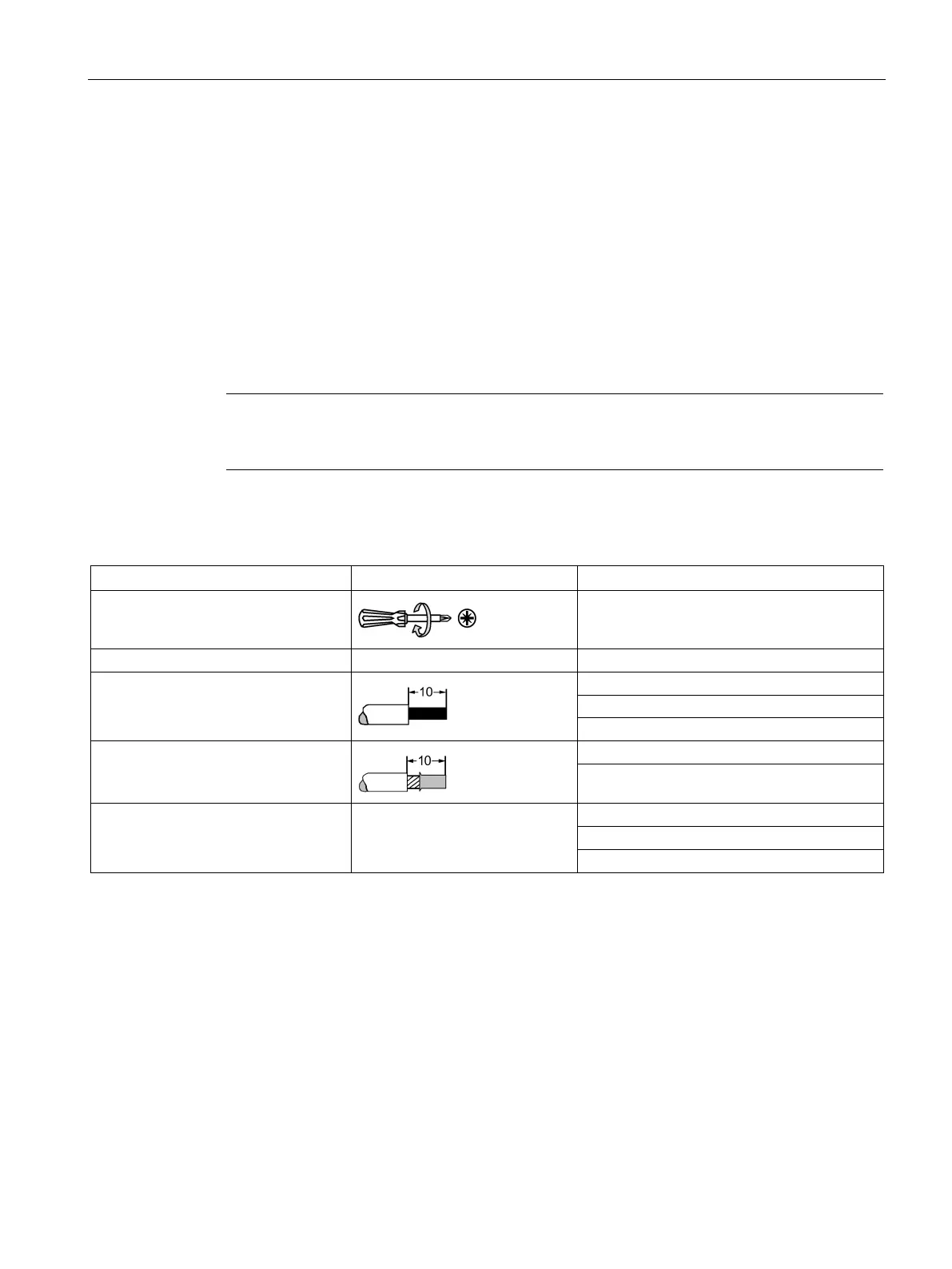
Table 8- 1 Main conductors of size S00
Tool
Pozidriv size PZ 2, Ø 5 to 6 mm
Solid and stranded
2 x (0.75 to 2.5) mm²
Finely stranded with end sleeve
2 x (0.5 to 1.5) mm²
2 x (0.75 to 2.5) mm²
AWG
1)
Only 1 conductor can be clamped on the stand-alone assembly support.

 Loading...