Functions
5.1 Protection against overload, phase failure, and phase asymmetry
SIRIUS 3RU thermal overload relays / SIRIUS 3RB electronic overload relays
Manual, 09/2016, A5E03656507420A/RS-AB/003
51
3RB20 / 3RB21 and 3RB30 / 3RB31 electronic overload relays
3RB20 / 3RB30 electronic overload relays are available for normal starting conditions in
tripping class CLASS 10E or for heavy-duty starting conditions in tripping class CLASS 20E
(all fixed settings).
3RB21 / 3RB31 electronic relays are suitable for normal and heavy-duty starting conditions.
A rotary switch is used to set the required tripping class (CLASS 5E, 10E, 20E or 30E)
dependent upon the prevailing starting conditions.
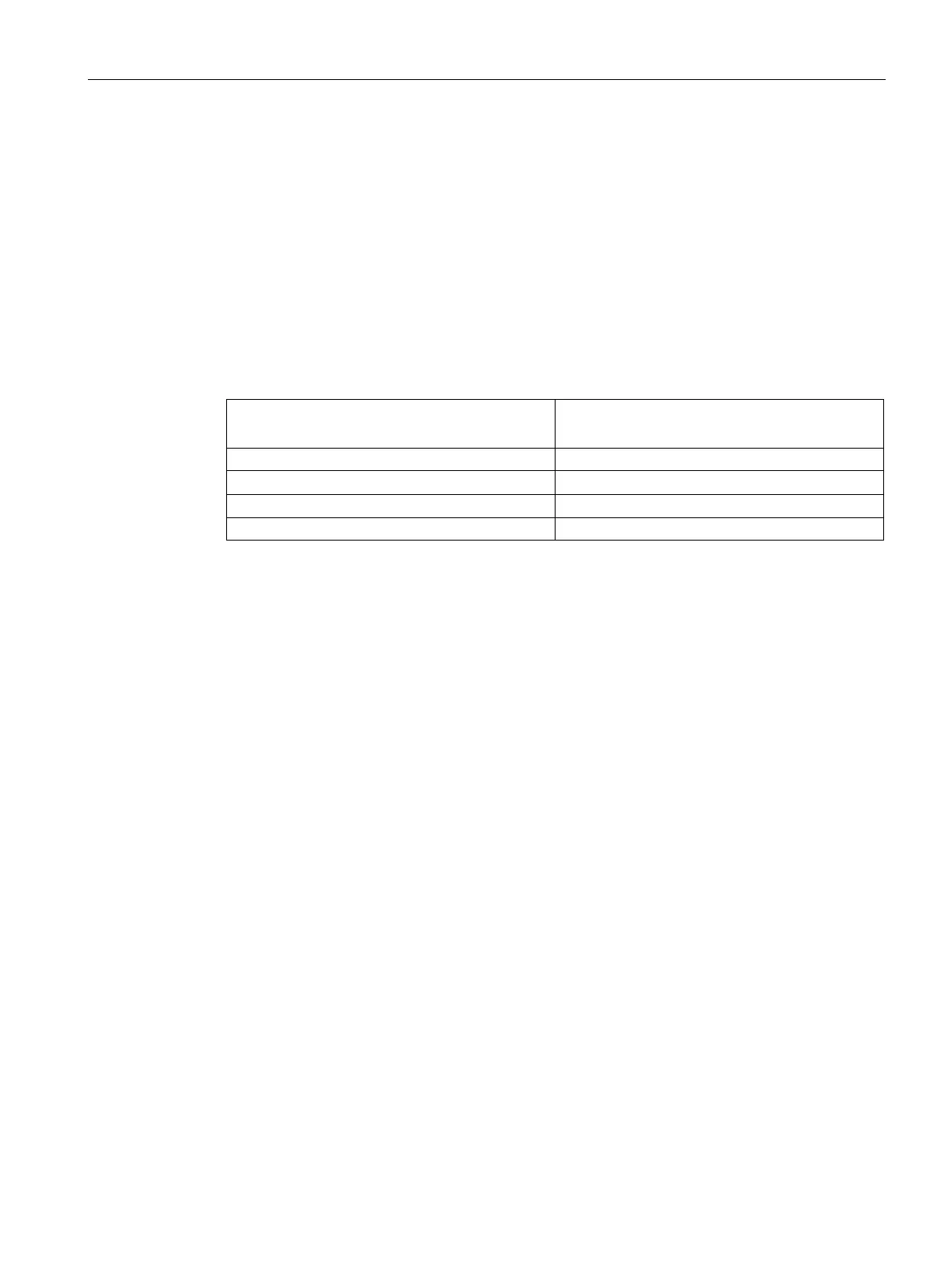
The tripping times according to IEC/EN 60947-4-1, tolerance band E, are as follows:
Table 5- 2 Tripping times dependent upon tripping classes according to standard
IEC/EN 60947-4-1, tolerance band E
Tripping time t
A
in s at
7.2 x I
e
from cold
CLASS 10E 5 < t
A
≤ 10
A
Tripping characteristics
Introduction
The tripping characteristic curves map the relationship between tripping time and tripping
current as a multiple of the current setting I
e
; they are specified for symmetrical 3-pole and
for 2-pole loading from cold.
The lowest current at which tripping will occur is known as the minimum tripping current. This
must lie within specific defined limits in accordance with IEC / EN 60947-4-1.
The limits for the tripping current in the case of the overload relays with symmetrical three-
pole loading are between 105 and 120 % of the current setting.
The limit tripping current determines the progression of the tripping characteristic curve up to
higher tripping currents based on the characteristics of the tripping classes (CLASS 10,
CLASS 20, etc., see the Chapter Tripping classes (Page 50)).

 Loading...