Power-Limited Guidelines
Make sure these guidelines are accounted for before wiring for power-limited systems:
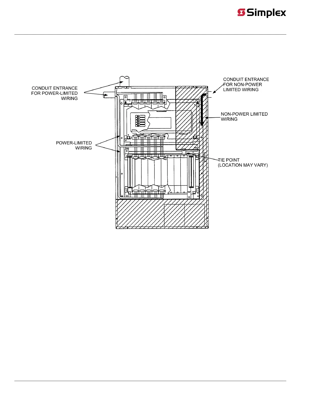
• Non-power limited field wiring (AC power, batteries, City connection) must be installed and routed in the shaded areas shown in Figure 16.
• Power-limited field wiring must be installed and routed in the non-shaded areas shown in Figure 16, with the exception of City wiring.
• Excess slack should be kept to a minimum inside the back box enclosure. The wiring should be neatly dressed and bundled together using the
wire ties provided with the equipment. Anchor power-limited wiring to tie points, as shown in Power-Limited Guidelines.
Figure 16: Power-Limited Wiring
• Tie the wiring located between bays to the internal wiring troughs, if applicable.
• When powering remote units or switching power through relay contacts, power for these circuits must be provided by a UPS-style power
supply, an ES-PS, an MSS, MSS2, or ESS (for 4010ES panels), or a power-limited power supply that listed for fire-protective signaling use.
• Supervised circuit rating is as follows:
- Standby Voltage Range @ Detector: 16.5 to 32 VDC
- Maximum Detector Standby Load Current: 3.0 mA
- Maximum Alarm (Short) current: 60 mA
- Maximum Line Resistance: 50 Ohms
- Ripple: 8% @ 120 Hz
- EOL Resistance: 3300 Ohms
• Auxiliary power only: In order to connect a circuit using power-limited wiring, the devices being powered must all be addressable, or a UL Listed
EOL relay must be used to supervise the circuit. Refer to Figure 17 for wiring directions for the EOL relay.
Note: The 2098-9739 Relay is used as an example. Other UL Listed EOL relays can be used, depending on the application.
page 17 579-205 Rev. H
4010ES and 4100 4120-Series Class A/Class B Zone Modules Installation Instructions
 Loading...