Installing into a 2975-91xx Expansion Bay
Review the following guidelines before mounting the motherboard into a 2975-91xx Expansion Bay.
• If a power supply is installed in the bay, it must be installed on the far right of the bay and any relay modules must be installed in the slots
immediately to its left.
• Relay cards must be installed in the rightmost possible slots. This is necessary to allow for the proper routing of non-power limited wiring
(typically 120 VAC wiring), which could be connected to a relay module.
• If a 4100-0155/4120-0155 SDACT, 4100-6052 Event Reporting DACT, 4100-6053 Point Reporting DACT, or a 4100-0153/4120-0153 CCDACT
is installed in the bay, it must be installed in the far left or far right slot. Neither of these modules contains the J1 or P1 connectors, which are
used to distribute power and communications to adjacent modules.
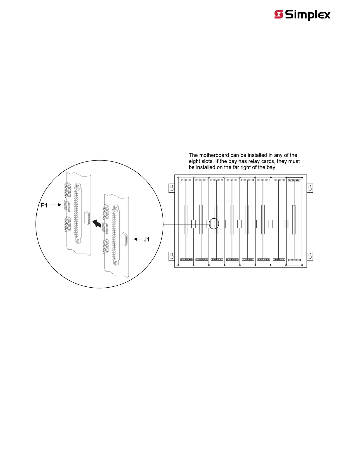
Use the following directions and Figure 4 to install a motherboard into an expansion bay.
1. Orient the motherboard with the connector labeled J1 on the right and the header labeled P1 on the left.
2. Match the connector on the previously installed motherboard with the pins on the motherboard you are installing. Slide the motherboard to the
left until the pins are completely inserted in the connector of the previously installed motherboard. If you are installing the leftmost board, the
pins will remain unconnected.
3. Secure the motherboard to the chassis with four torx screws.
The motherboard can be installed in any of the eight slots. If the bay has relay cards, they must be installed on the far right of the bay.
Figure 4: Installing the Motherboard into a 4100 Expansion Bay
4. If you are installing the leftmost motherboard, connect a 733-525 Power and Communication Harness. Continue to the next topic to connect the
harness.
Connecting the 733-525 Harness
If you need to connect a 733-525 Harness to a motherboard, refer to Figure 4 and follow these steps. Make sure to route the power and
communication wiring on the left side of the bay.
1. Connect one end of the harness to a motherboard in an adjacent bay. If the adjacent bay is a master controller bay, connect the harness to the
P2 and P3 connectors of the master controller motherboard and continue to step 2. If the adjacent bay is an expansion bay, connect the harness
to the P2 and P3 connectors of the motherboard installed in the leftmost slot. (If a a 4100-0155 /4120-0155 SDACT, 4100-6052 Event Reporting
DACT, 4100-6053 Point Reporting DACT, or a 4100-0153/4120-0153 CCDACT occupies the leftmost slot, connect the harness to the motherboard
in the second slot from the left.) Connect the harness as follows:
a. Insert the harness connector with the blue wire into the P2 connector. Note that the P2 connector has eight pins. Insert the harness
connector on either the top four pins or the bottom four pins, not in the middle.
b. Insert the harness connector with the white wire into the P3 connector. Note that the P3 connector has eight pins. Insert the harness
connector on either the top four pins or the bottom four pins, not in the middle.
2. Connect the other end of the harness to the leftmost motherboard in the next bay, as described below. Make sure to route the wiring on the left
side of the bay.
a. Insert the harness connector with the blue wire into the P2 connector. Note that the P2 connector has eight pins. Insert the harness
connector on either the top four pins or the bottom four pins, not in the middle.
b. Insert the harness connector with the white wire into the P3 connector. Note that the P3 connector has eight pins. Insert the harness
connector on either the top four pins or the bottom four pins, not in the middle.
page 5 579-205 Rev. H
4010ES and 4100 4120-Series Class A/Class B Zone Modules Installation Instructions
 Loading...