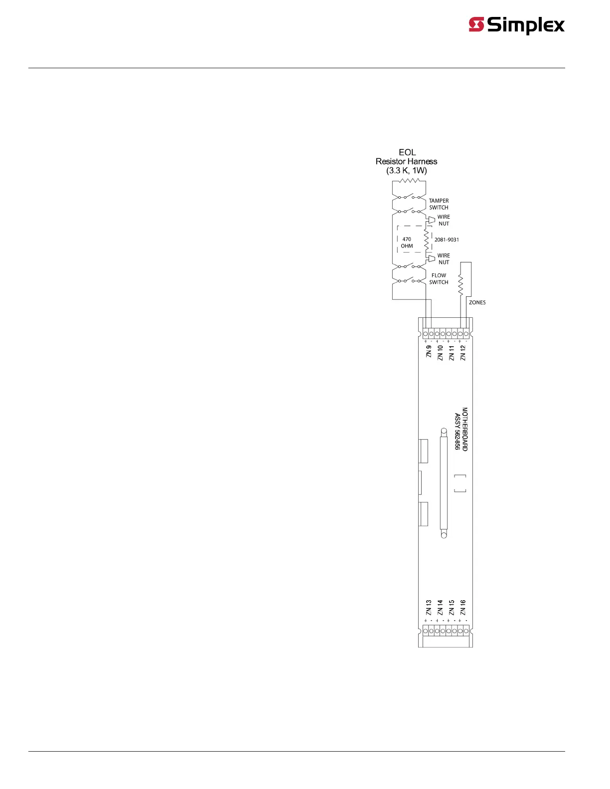
Wiring for One Zone
Figure 22 shows a waterflow and tamper switch, both of which are normally open devices, wired to a single Class B monitor zone ( 4100-5001,
4100-5004, 4100-5005 or 4010-9920). Adhere to both the general wiring guidelines outlined earlier in this document and the specific wiring guidelines
listed below.
Note: Both devices must be NO. A combination of NC and NO devices is not allowed on the same zone. The programming point type for this
application is WSO.
Specific Guidelines for Wiring a Waterflow Switch to a Class B Zone
Module
• 4081-9002 EOL Harness (not the 378-017 EOL Resistor) is
required at the last device.
• If a zone is not used, connect a 3.3 K, 1 W (378-017) resistor across
zone terminals.
• Connect devices to the appropriate zone. The zone shown in the
figure is an example.
• Each zone is marked with its circuit number. Refer to the 4100
Programmer Report, which references the exact wires connected.
• All tamper switches must be located after a 470 Ohm resistor, as
shown in the figure.
Figure 22: Class B Monitor Zone – Waterflow
Switch Wiring (4081-9002 EOL resistor harness)
Class B N.C Tamper Switch Wiring – Non ULC and Non UL 9th Edition Legacy Systems
Only
This section shows how to connect the zone module to Normally Closed tamper switches using Class B wiring.
page 23 579-205 Rev. H
4010ES and 4100 4120-Series Class A/Class B Zone Modules Installation Instructions
 Loading...