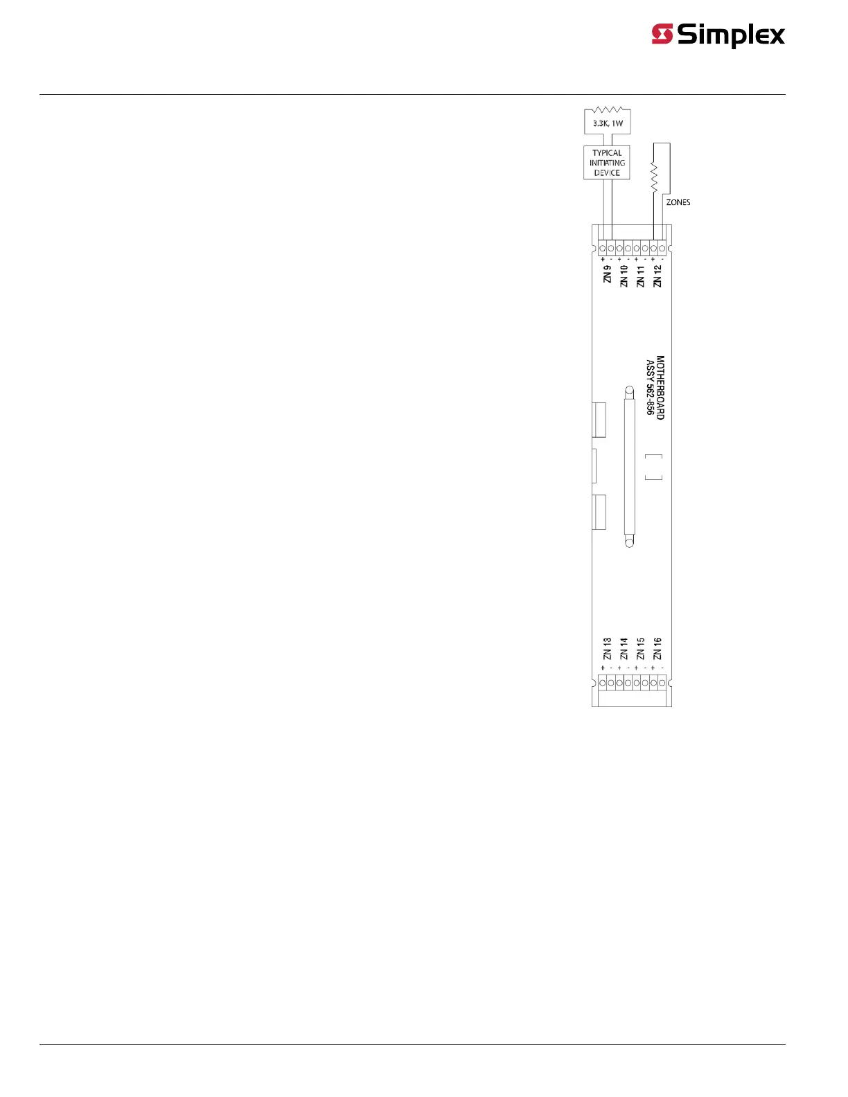
Specific Wiring Guidelines for Class B Zone Modules
• If a zone is not used, connect a 3.3 K, 1 W resistor (378-017) across zone
terminals as shown in the figure.
• 4081-9002 EOL Harness (not the 378-017 EOL Resistor) is required at the last
device.
• All device wiring must be terminated to the appropriate zone as shown on Zone
1.
• Wiring shown in the figure is typical. All detector types may be wired to any zone.
• Each zone is marked with its circuit number. Refer to the 4100 Programmer Report,
which references the exact wires connected.
• For zones that connect contacts only, the maximum line resistance is 800 Ohms.
Figure 20: Class B Monitor Zone Wiring
(4081-9002 EOL resistor harness)
Class B N.O. Waterflow and Tamper Switch Wiring
This section shows how to connect the zone module to waterflow switches and tamper switches, either in separate zones or in the same zone, using
Class B wiring.
Wiring for Separate Zones
Figure 21 shows an NO waterflow switch and an NO tamper switch wired to separate Class B monitor zones (4100-5001, 4100-5004, 4100-5005 or
4010-9920).
Adhere to both the general wiring guidelines outlined earlier in this document and the specific wiring guidelines listed below.
page 21 579-205 Rev. H
4010ES and 4100 4120-Series Class A/Class B Zone Modules Installation Instructions
 Loading...