Regent / 500 / 2500 / LT Series
TP 300-4218-04-RG-SMAN 1/200626
Transmission Drive Belt
Replacement
REMOVE THE OLD BELT
1. Turn off the PTO, stop the engine, block the tires, and
engage the parking brake.
2. Remove the mower deck.
3. Remove the hood. See Hood Removal and
Installation.
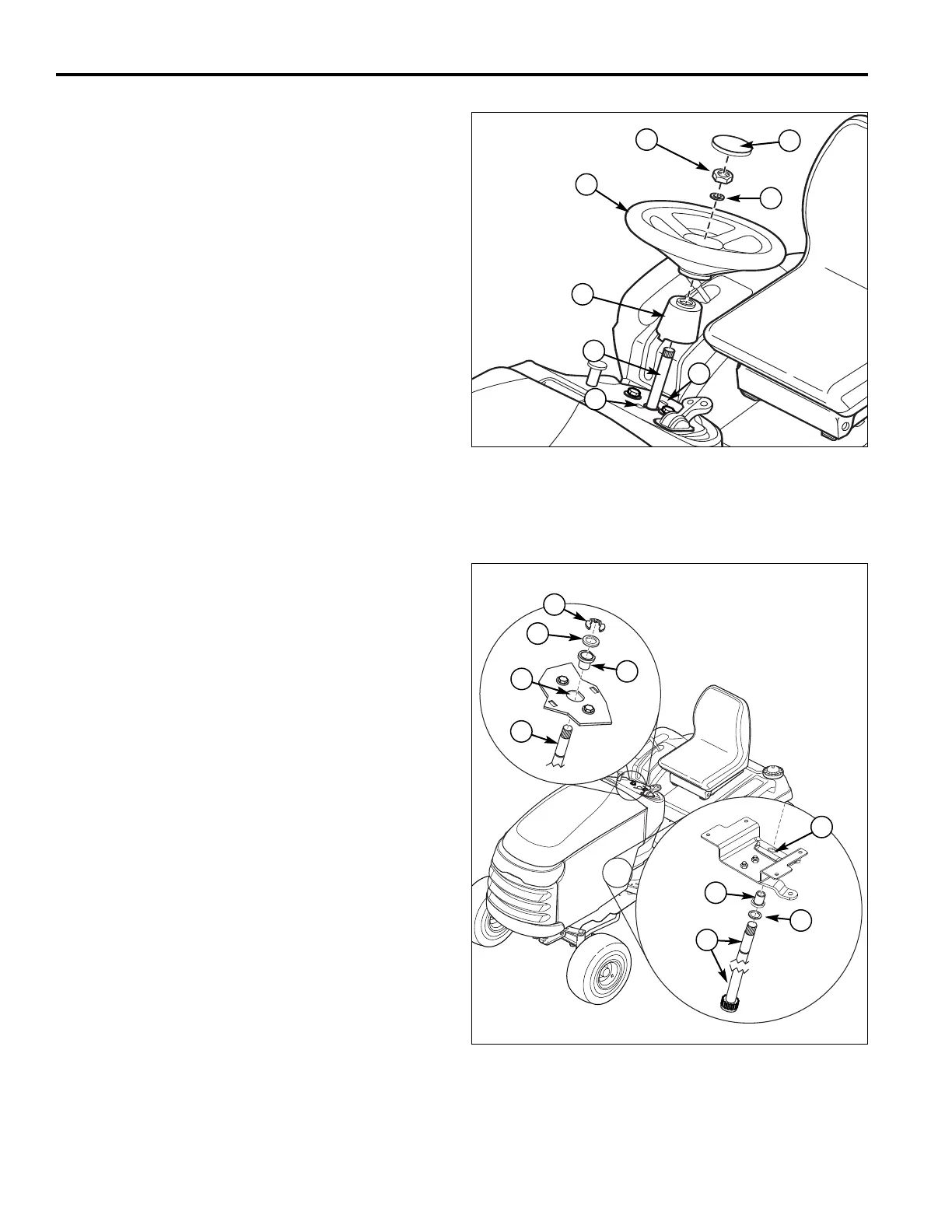
4. Remove cap (A, Figure 53), nut (B) and washer (C).
Remove and discard nut (B). Do not reuse nylock
type nuts on critical components such as
steering.
5. Remove steering wheel (F) from steering shaft (D).
THis may require a tap with a soft faced hammer from
underneath.
6. Squeeze together the base of shaft cover (E) to
remove it from holes (G) in dash.
7. Block rear wheels and raise the front of the tractor.
8. Hold or support steering shaft (D, Figures 53 & 54)
from the under side of the tractor.
9. Remove clip (A, Figure 54) and washer(s) (B).
10.Slide steering shaft (D, Figure 54) out. Remove
washer(s) (B) and bushing (C).
11.Unplug the PTO clutch plug (C, Figure 55). Remove
the capscrew (F) and related hardware securing the
PTO clutch to the crankshaft. Remove the clutch.
12.Remove the drive belt from the engine pulley (A,
Figure 58), idler pulleys (C), and transmission input
pulley (B).
INSTALL THE NEW BELT
1. Install a new drive belt on the transmission input
pulley (B, Figure 58) and engine drive pulley (A).
2. Install the PTO clutch using the original hardware as
shown in Figure 55. Be sure the engine pulley key
(A) is installed as shown in the inset. Torque the
crankshaft bolt (F) to 45-50 ft lbs (61-67Nm).
3. Install the drive belt in the idler assembly pulleys (C,
Figure 55). Tighten the pulley hardware.
4. Set bushing (C, Figure 54) into tower dash hole (E).
Both flat edges must be in line for proper fit. See
Figure 56.
5. Slide washer (B, Figure 54) and bushing (C) onto
steering shaft (D).
6. Slide shaft (D) with washer (B) and bushing (C)
through lower bracket (F).
7. Guide shaft (D) through tower (E) and bushing (C).
8. Guide bushing (C) through bracket (F). Both flat
edges must be in line for proper fit. See Figure 56.
Figure 53. Transmission Drive Belt Replacement
A. Cap E. Shaft Cover
B. Nut F. Steering Wheel
C. Washer G. Holes
D. Steering Shaft
E
Figure 54. Steering Shaft
A. Clip D. Steering Shaft
B. Washer(s) as required E. Tower & Dash Hole
C. Bushings F. Lower Bracket
A
C
B
F
D
D
E
C
A
B
F
B
C
D
G
G
 Loading...