071807 VI. Figures
30
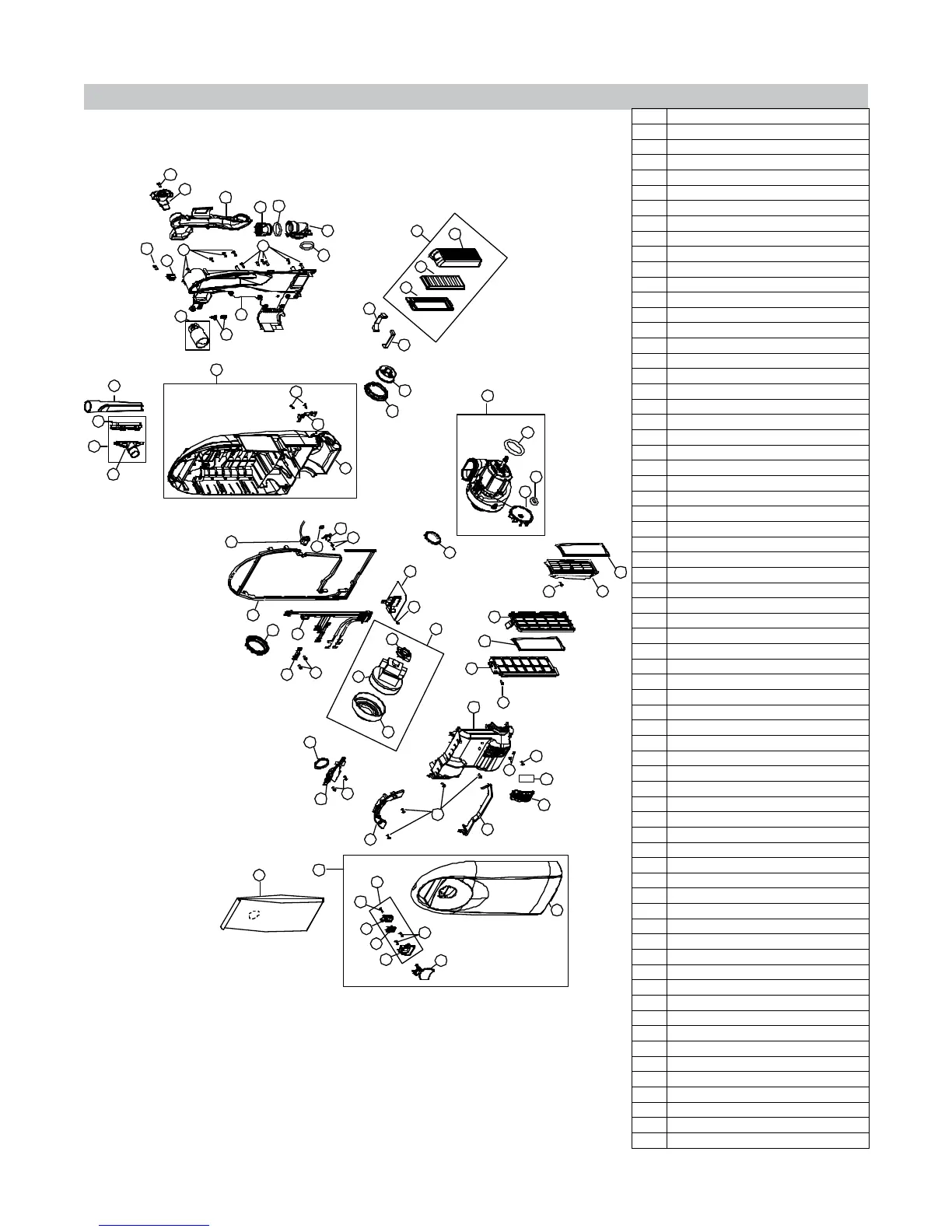
O. Body Assembly
1
2
3
4
6
8
9
10
16
17
18
19
22
20
21
23
28
29
30
31
32
33
56
56
56
56
56
56
56
35
37
38
30
36
52
39
40
41
42
43
44
7
62
3a
3b
3c
57
56
34
5
13
14
56
56
15
11
12
60
59
58
53
54
55
46
45
48
56
47
49
56
51
61
56
50
24
27
25
26
1 Dust Cover Assembly
2 Printed Dust Cover
3 Dust Cover Latch Body Assembly
3a Dust Cover Latch Body
3b Dust Cover Latch
3c Latch Cover
4 Dust Cover Lever
5 HEPA Bag
6 Carrying Handle
7 Motor Cover Seal
8 Direct Air Filter Cover
9 Direct Air Motor Filter
10 Motor Cover
11 Internal Air Path
12 Secondary Filter
13 Secondary Filter Frame
14 Post Filter Mount
15 Post Filter Seal
16 Bag Mount
17 Bag Mount Seal
18 Clean Air Motor Mount Rear
19 Clean Air Motor
20 Clean Air Motor Mount Front
21 Clean Air Motor Assembly
22 Printed Circuit Control Board
Main PCB - Hall Sensor (X9.5/6)
23 Direct Air Motor Inlet Seal
24 Direct Air Motor Assembly
25 Direct Air Cleaning Fan
26 Fan Washer
27 Direct Air Motor Shroud Seal
28 Internal Wire Harness
29 Dust Cover Catch
30 Pivot Bushing - Casting
31 Primary Dust Compartment Seal
32 Winged Rocker Switch
33 Thermal Reset Switch
34 Thermal Switch Seal
35 Dust Compartment
36 Inner Wire Guide
37 Tilt Lock Body Plate
38 Dust Compartment Assembly
39 Pleated Post Filter Base
40 Post Filter
41 Pleated Post Filter Cover
42 Pleated Post Filter Base Assembly
HEPA Plus Post Filter Base Assembly
43 Motor Outlet Dust Compartment Seal
44 Motor Outlet Back Plate Seal
45 Hose Inlet Elbow
Hose Airpath Seal (Not Shown)
46 O-Ring Hose Inlet Elbow Seal
47 Hose Inlet Cuff
48 O-Ring Hose inlet Cuff Seal
49 Air Hose Path
50 Rotational Valve Handle
51 Roto Valve Switch
52 Crevice Tool
53 Back Cover
54 Crevice Tool Clip
55 Rotational Valve
56 Screw
57 Screw
58 Upholstery Tool Assembly
59 Dust Brush Attachment Assembly
60 Combo Tool Assembly
61 Screw
62 Adjustment Hole Plug f/Circuit Board
 Loading...