User Manual of A90 Series Inverter
209
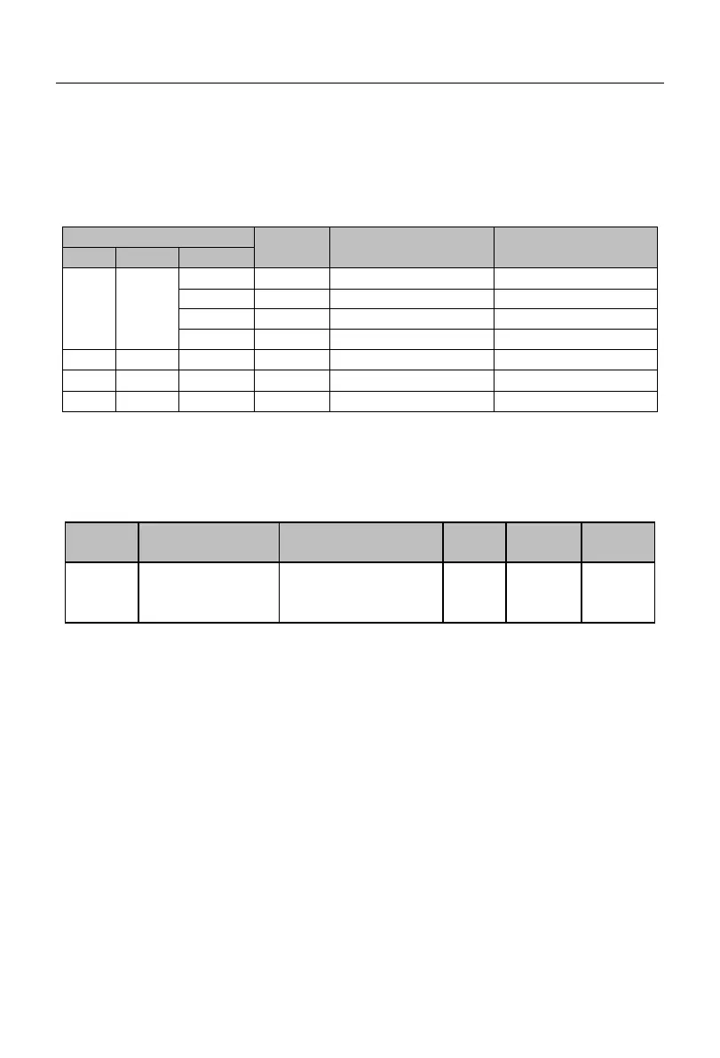
PID settings are determined in conjunction with the setting of the function code F09.00.
The A90 series inverter has a multi-segment PID setting function, and its switching
conditions are mainly dependent on the input functions “15: multi-segment PID terminal 1”
and “16: multi-segment PID terminal 2”, as detailed in Table 7-16.
Table 7-16 Details of Multi-segment PID Setting Function
7.11 Communication Function Parameter Group of F10 Group
The A90 series inverter supports the RTU format Modbus protocol, and the
“single-master multi-slave” communication network with RS-485 bus.
Local Modbus
communication
address
1-247; 0: broadcast
address
For the entire communication network, the inverter as a slave must have its own
unique address. Its setting range is 1 to 247. That is, a network supports 247 slave stations
at most.
★
0 is the broadcast address, which does not need to be set. All slave inverters can be
recognized.
The slaves and hosts attached to the same network must follow the same sending and
receiving principles (e.g. baud rate, data format, and protocol format) to ensure normal
communication. Hence, there are three corresponding function codes, i.e. F10.01 (baud
rate), F10.02 (data format) and F10.10 (protocol format, Modbus-RTU protocol by default
for the A90 series inverter). The devices connected to the network must have the same
settings.
 Loading...