User Manual of A90 Series Inverter
60
(F04.19=0), the logic diagram is as shown in Fig. 5-3(d).
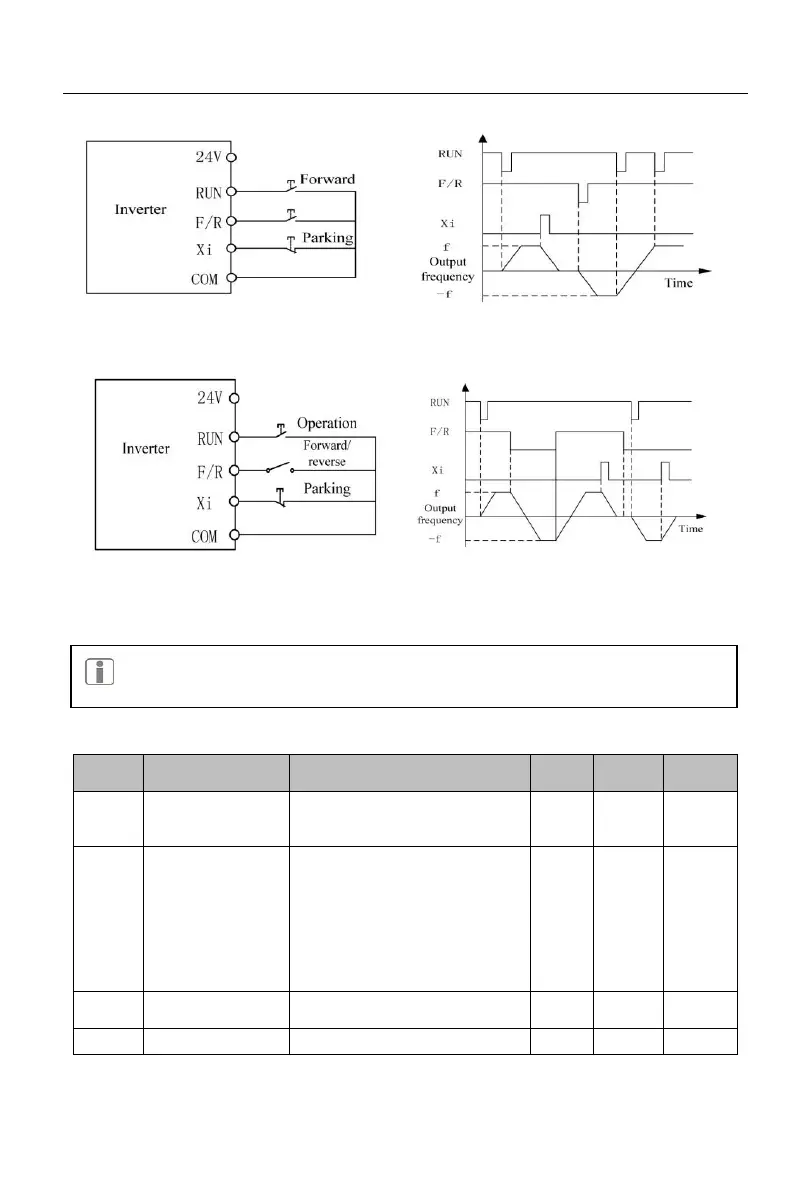
(a) Wiring diagram of three-line control (F00.03=2)
(b) Forward/reverse control logic
(F04.19=0, F00.03=2)
(c) Wiring diagram of two-line control (F00.03=3) (d) Forward/reverse running logic
(F04.19=0, F00.03=3)
Fig. 5-3 Three-line Control
The three-line control logic of the A90 series inverter is consistent with the
conventional electrical control. The keys and knob switches should be used
correctly as shown in the schematic diagram. Otherwise, operation errors may be caused.
5.6 Common Process Parameters of Inverter
Drive control mode
of motor 1
0: V/F control (VVF)
1: Speed sensorless vector
control (SVC)
Options of main
frequency source A
0: digital frequency setting
F00.07
1: AI1 2: AI2
4: VP (keyboard potentiometer)
6: Percentage setting of main
frequency communication
7: Direct setting of main
frequency communication
Digital frequency
setting
0.00 to maximum frequency
F00.16