29
|
Instruction Manual and Parts List
6.2
Components
No.
Part No.
Description
QTY
2
3
4
5
6
7
8
9
10
12
13
14
15
16
17
18
19
20
22
23
24
25
26
27
28
29
31
32
33
34
35
36
1
1
1
1
2
1
1
1
2
1
1
2
1
2
1
1
2
1
0
1
4
1
1
2
1
1
1
2
1
1
1
11-80151550-01
1281-01-30
21-08008160-01
11-60181630-01
31-04424000-09
11-80181650-01
11-80160610-01
101-02-15
1281-01-13
1255-02-10
11-80160810-01
11-80150710-01
101-02-33
11-80160710-01
25-20000000-08
11-00161120-01
101-06-02
101-06-04
11-10090620-01
12-80500612-01
1283-05-06-00
1283-05-08-00
1283-01-01-03
12-60401422-01
1283-01-01-02A
12-80600812-01
32-14450300-09
1281-01-04
1283-01-02
1281-01-40
1281-01-39A
12-60505022-01
1281-02-09-1
11-40120925-01
Set screw SM 15/64 x 28 L=11
Thread take-up lever assembly
Counter weight protecting plate
Scew SM 9/32 x 28 L=16
O ring
Set screw SM 9/32 x 28 L=16
Screw SM 1/4 x 40 L=6
Needle bar crank
Main shaft bushing (left)
Driving wheel
Screw SM 1/4 x 40 L=8
Set screw SM 15/64 x 28 L=7
Main shaft bushing (middle)
Thrust collar D=14.72 W=12
Screw SM 1/4 x 40 L=7
Snap ring
Screw SM 1/4 x 40 L=11
Feed drive eccentric cam
Thrust collar
Screw SM 9/64 x 40 L=6
Bolt socket M5 L=6
Electronic control unit assembly (220V)
Electronic control unit assembly (220V)
Hand wheel
Screw M4 L=14
Motor stator
Motor rotor
Set screw M6 L=8
Oil seal
Supporting sleeve
Main shaft
Roller felt
Oil seal pin
Bolt sock
et M5 L=50
Rear wire cover
Screw SM3/16 x 28 L=12
20
30
1
1
1
1
2
1
1
1
2
1
1
2
1
2
1
1
2
0
1
1
4
1
1
2
1
1
1
2
1
1
1
Arm Shaft
and Thread
Take-Up Lever
1255-02-12
1280-01-02-02A
1
21
11
30
1
1
2
2
2
2
1
1
1 1
12-60501522-01
Bolt socket M5 L=15
1
1
20
30
CE
CF
0
1
1
1
2
1
1
1
2
1
1
1
1
1
2
1
2
0
0
2
0
1
1
2
4
1
1
2
1
1
1
2
1
1
1
2
1
4
1
1
2
1
1
1
2
1
1
1
2
1
0
1
1
1
2
1
1
1
2
1
1
2
1
1
1
1
2
0
0
2
1
0
1
2
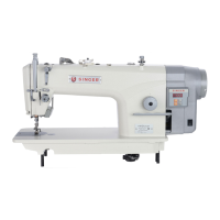
Integrated Energy Saving Direct Drive Lockstitch Sewing Machine
37
1
0
Electronic control unit assembly (110V)
Electronic control unit assembly (110V)
0
1
0
1
1
0
1283-05-06-01
1283-05-08-01
 Loading...