10 11
PART II: POLAR ALIGNMENT
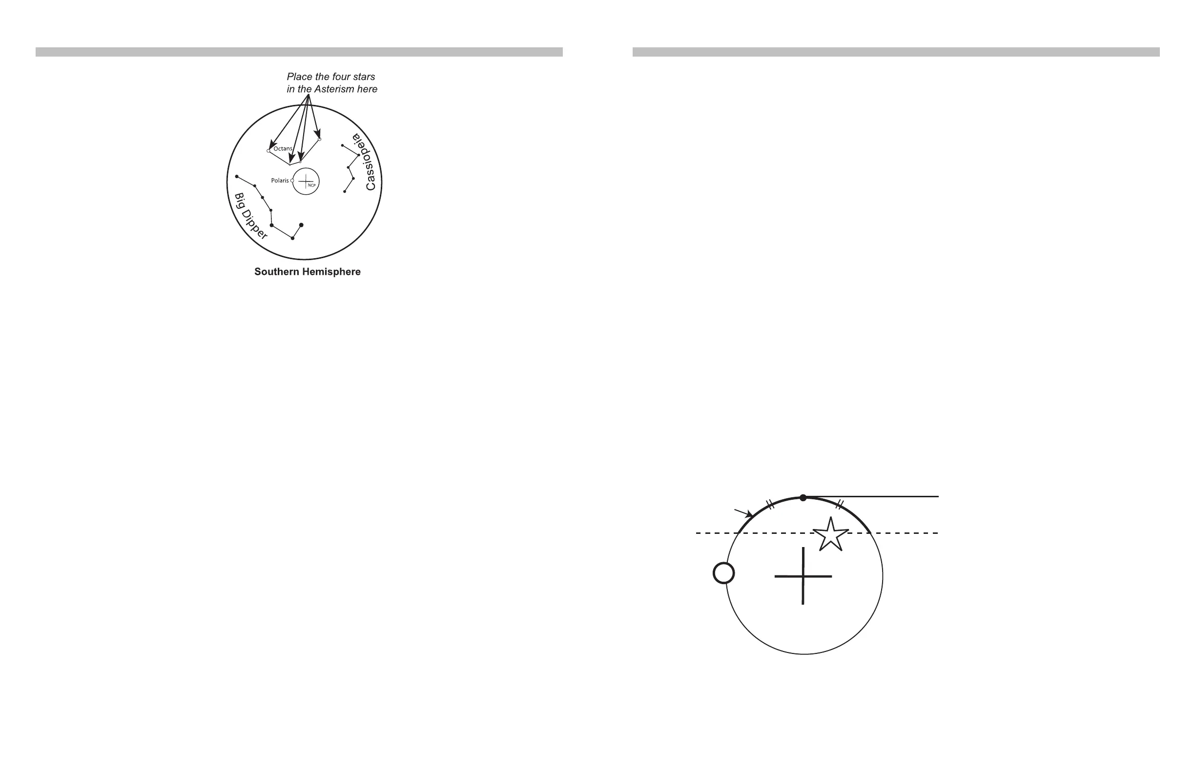
Fig. 2.3b
• For observing in Northern Hemisphere: Find the Polaris (The brightest star near the
North Celestial Pole) in the polar scope; then use the jackscrew and the two azimuth
adjustment knobs to move the Polaris to the proper position in the FOV of the polar
scope. (Refer to the upcoming section “The Orientation of Polaris in Polar Scope”).
• For observing in Southern Hemisphere: In the FOV of the polar scope, locate the 4
dim stars (Around Magnitude 5 to 6) which form the pattern like the “Octans” drawing
in the polar scope (refer to Fig. 2.3b). Rotate the large knurled ring of the polar scope
assembly to align the orientation of the “Octans” drawing to the 4 stars. Then use the
jack screw and the azimuth adjustment knobs to move the 4 stars to the 4 small circles
of the “Octans” drawing.
5. Tighten the primary locking knob, and then tighten the azimuth locking screws, the fork
gripping knobs and screws.
6. It is recommended to remove the jackscrew handle after the polar-alignment has nished.
It can prevent unexpected changes to the polar-alignment.
2.4 The Orientation of the Polaris in Polar Scope
As the Polaris is not located exactly at the North Celestial Pole, we can see it orbits the North
Celestial Pole in a polar scope. The large circle seen in the center of the pattern in Fig. 2.3b is
a representation of the Polaris’ orbit around the North Celestial Pole. When performing the po-
lar alignment process, it is necessary to determine the orientation of the Polaris on the circle.
We can use the following 3 methods to get the orientation:
1. Locate Ursa Major (Big Dipper) in the sky, or alternatively Cassiopeia. Tighten the R.A.
clutch again. Rotate the large knurled ring of the polar scope assembly until either the Big
Dipper or Cassiopeia is aligned with their pattern in the FOV of the polar scope. At this
point, the location of the small circle on the large central circle of the pattern represents the
orientation of the Polaris in the polar scope. Put the Polaris to the center of the small circle
to nish the polar alignment.
2. Locate both the Polaris and the Kochab in the sky near the North Celestial Pole. The di-
rection from the Polaris to the Kochab can be used as proximity of the orientation of the
Polaris in the polar scope. Put the Polaris to the same direction on the large central circle
in the polar scope to nish the polar alignment.
3. At the end of the initialization of the SynScan hand control, after entering the proper local
longitude, latitude, date, time, and daylight-saving time, the SynScan hand controller will
display the message: “Polaris Position in P.Scope=HH:MM”. Imagine the larger circle in Fig.
2.3b as a clock’s face with 12:00 at the top, with the current time pointing to the “HH:MM”. The
orientation of the hour hand of the clock represents the orientation of the Polaris in the polar
scope. Put the Polaris to the same orientation on the large circle to nish the polar alignment.
Tips: To nd the top of the large circle in FOV of the polar scope, use the latitude jackscrew to
move the Polaris close to the top of the circle, and then use the azimuth adjustment knobs to move
the Polaris in the FOV horizontally. The middle point of the arc which was cut by the horizontal track
of the Polaris is the top of the large circle (Fig 2.4).
PART II: POLAR ALIGNMENT
Out of the three methods above, the rst two methods are somewhat less accurate, while the
orientation given by the SynScan hand controller is the most accurate.
Fig. 2.4
Top Point
Horizontal track of the Polaris
Arc
 Loading...