SkyTrac Systems Ltd.
Document Rev. 01.020 DOC0334 Page 32 of 49
Restricted Proprietary and Confidential Information
4.2.11 Audio Lines
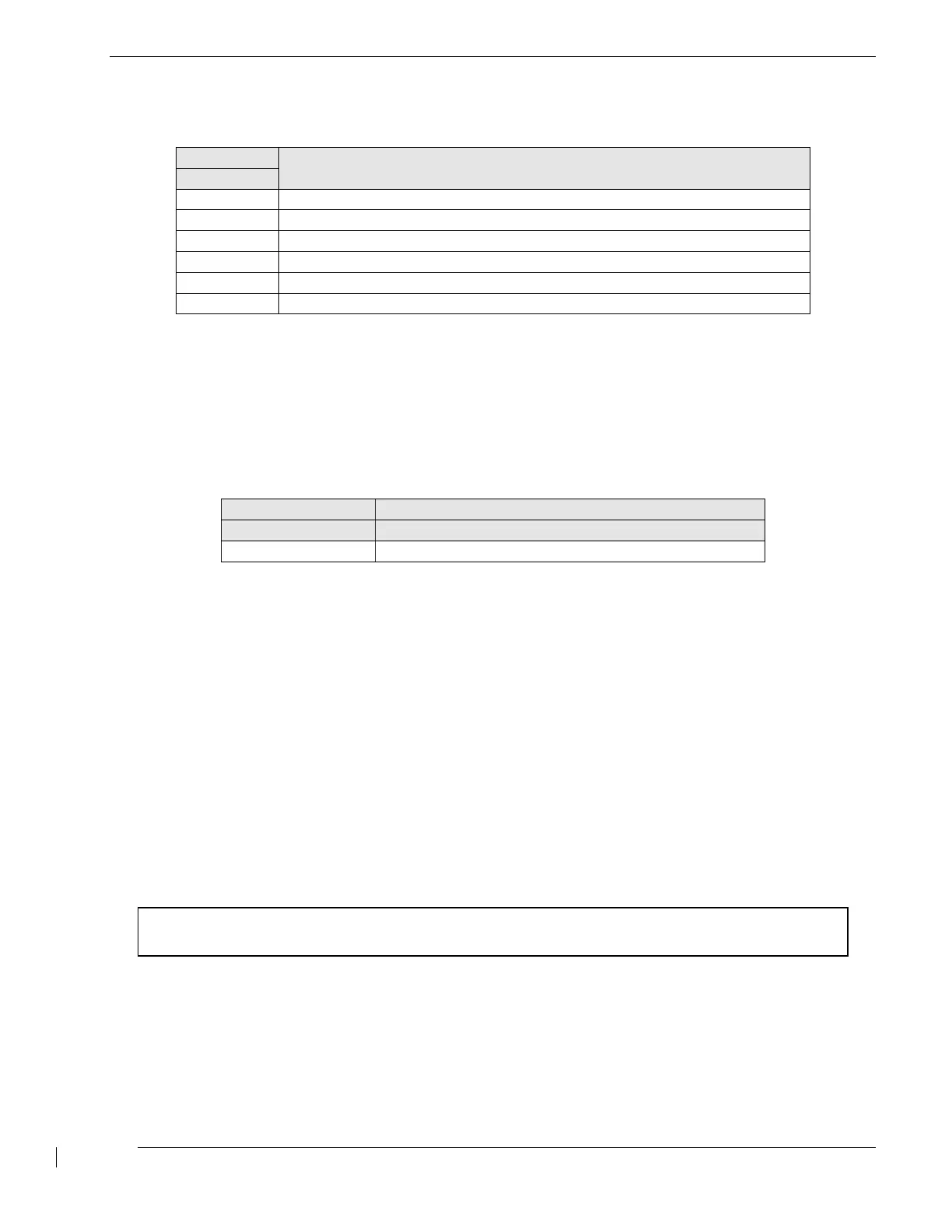
Table 28—Audio Line Description
Description and recommended usage
Microphone positive input
Microphone negative input
Speaker positive 600 ohm output
Speaker positive 300 ohm output
4.2.12 ITRAY-200 Communication Lines
The ISAT-200 has several pins which communicate with the Configuration Module on the ITRAY-
200. These pins are pre-wired at the factory and are not for use by the aircraft installer.
Table 29—ITRAY-200 Communication Line Description
Description and recommended usage
Power supply and data bus to ITRAY-200
4.3 Example Installation drawings and BOM
Approved installation drawings from the appropriate STC should be used for installation of the ISAT-
200 System.
Please refer to the ISAT-200 System Installation Reference Drawings (DOC0461) for reference
when an STC is not applicable.
4.3.1 ISAT-200 Installation Wiring Diagram Notes
The following notes pertain, in general, to the ISAT-200 Installation Wiring Diagram Illustrations.
All signal and power shield continuity must be individually maintained through bulkhead disconnects.
Please refer to the ISAT-200 System Installation Reference Drawings or STC drawings for additional
installation notes.
IMPORTANT NOTICE:
All system interconnect cables must be connected before power is applied to the system.
The document reference is online, please check the correspondence between the online documentation and the printed version.
 Loading...