-13-
No.SFOD-OMT0006-F
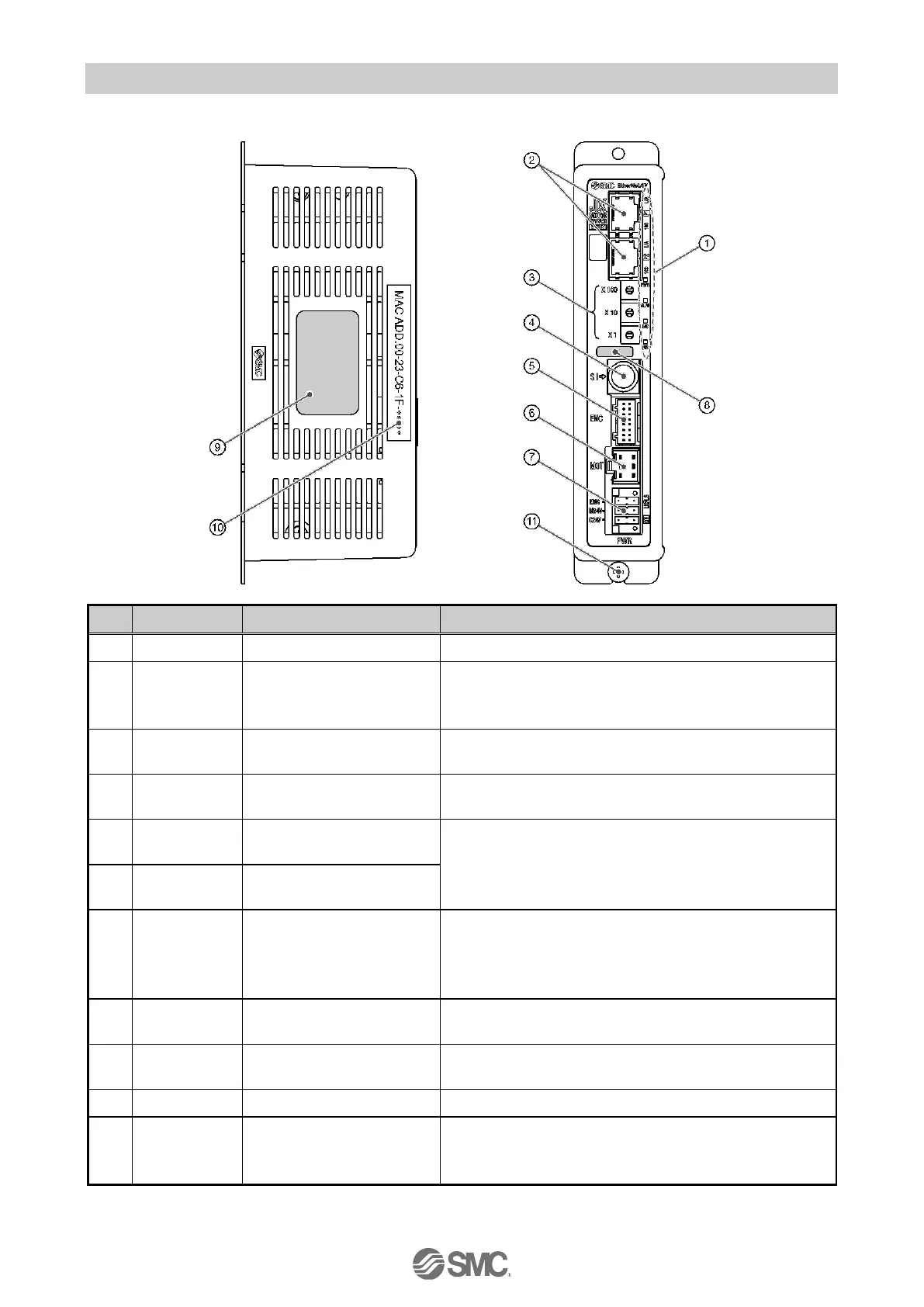
3.2 Parts Description
Details of the parts of the controller.
LED’s to indicate the controller status.
EtherNet/IP
communication
connector
Switches to set the EtherNet/IP communication IP
address (0 to 255) by X1, X10 and X100.
Serial I/O connector
(8 poles)
Connector for the teaching box (LEC-T1) or the
controller communication cable (JXC-W2A-C).
Encoder connector
(16 poles)
Connect to the actuator cable.
Motor driving connector
(6 poles)
Power supply connector
(5 poles)
Connect to the controller power supply (24VDC)
using the power supply plug.
Control power (+), Stop signal (+), Motor power (+),
Lock release (+), Common power (-)
Applicable actuator part
number label
Label indicating the actuator part number which can
be connected to the controller.
Controller part number
label
Label indicating the controller part number.
EtherNet/IP MAC address is displayed.
Functional Ground
(When the controller is mounted, tighten screws
and connect the grounding cable)

 Loading...


