EasyManuals Logo
Home>SMC Networks>Controller>JXC91

SMC Networks JXC91 User Manual

SMC Networks JXC91
86 pages
To Next Page IconTo Next Page
To Previous Page IconTo Previous Page
Page #30 background imageLoading...
Page #30 background image
-29-
No.SFOD-OMT0006-F
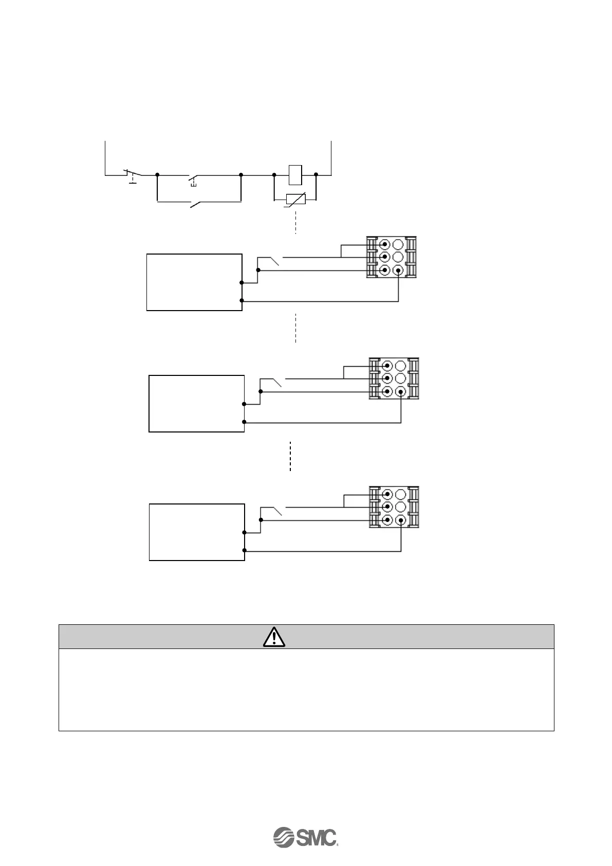
(3) Motor power shutdown (relay contact (2))
If it is necessary to have a circuit to shutdown the motor power externally, relay contacts should be
made between the 24VDC controller power supply and the M24V and EMG terminal of the power
supply plug.
Warning
(1) Relay contacts should be made between the 24VDC controller power supply and the M24V and
EMG terminal of the power supply plug. The actuator may make unexpected movement.
(2) Do not perform return to origin (SETUP) when motor drive power (M24V) is disconnected.
The controller cannot recognize the correct origin point if a return to origin instruction is made with
the motor drive power (M24V) disconnected.
(3) Do not energize the LK RLS terminal while the motor drive power (M24V) is disconnected.
(Circuit example)
24VDC
Ry
0V
Stop
Switch
Surge suppressor
The stop is
released switch
Power supply plug 2
Power supply plug 3
Power supply plug 1
LK RLS (6)
Ry
(1) C 24V
(2) M 24V
0V (4)
(3) EMG
Controller
Input power
supply
DC24V
0V
LK RLS (6)
Ry
(1) C 24V
(2) M 24V
0V (4)
(3) EMG
Controller
Input power
supply
DC24V
0V
LK RLS (6)
Ry
(1) C 24V
(2) M 24V
0V (4)
(3) EMG
Controller
Input power
supply
DC24V
0V

Table of Contents

Questions and Answers:

Question and Answer IconNeed help?

Do you have a question about the SMC Networks JXC91 and is the answer not in the manual?

SMC Networks JXC91 Specifications

General IconGeneral
BrandSMC Networks
ModelJXC91
CategoryController
LanguageEnglish

Related product manuals