-51-
No.SFOD-OMT0006-F
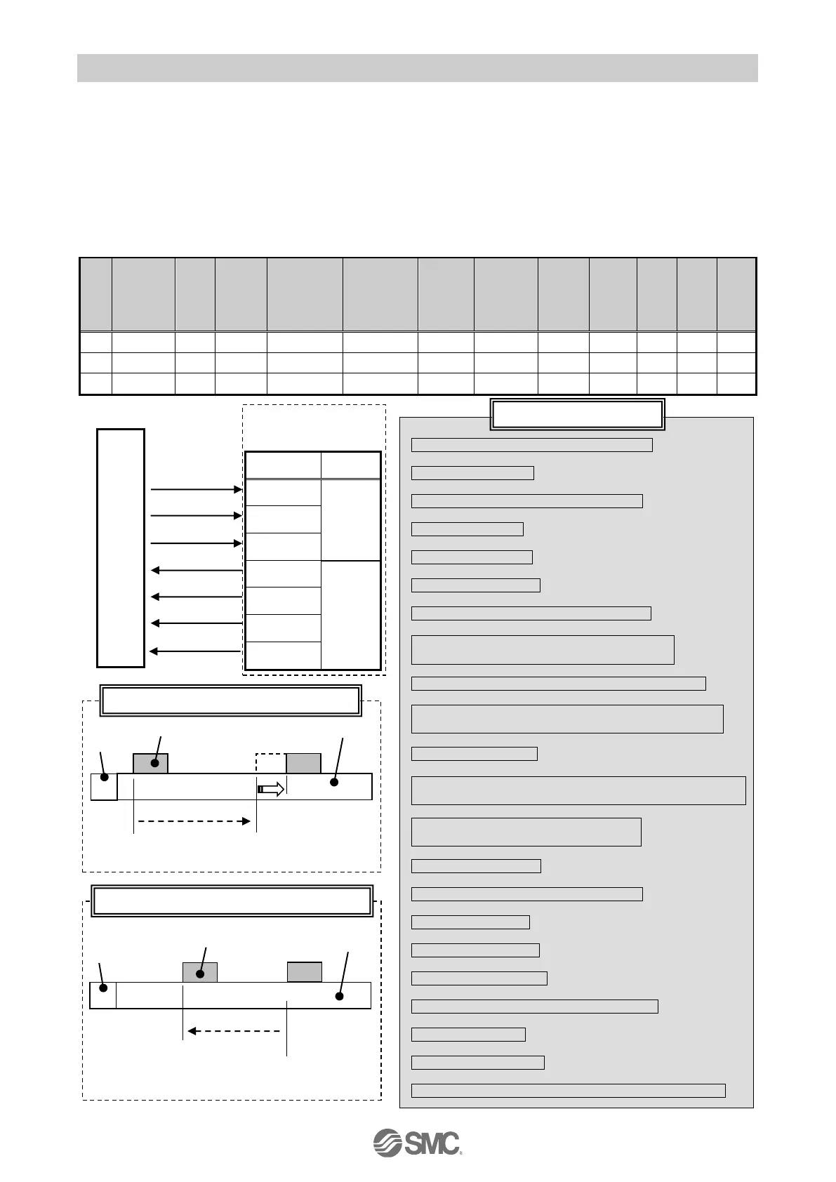
12.2 Pushing Operation
Eg.) Move the actuator from the origin to a point 100 mm away at 100 mm/s. (Step Data No.1 is used for this
operation).
From the 100 mm point, the actuator must start a pushing operation of 10 mm/s speed and 50% or less
force.
(the pushing distance is up to 5 mm).
Then, the actuator should move from the position where the pushing operation was completed (where
“INP” turned ON) to a point 50 mm away at 50 mm/s.
(Step Data No.2 is used for this operation).
■[Normal mode] Step data example
(1) Select/input Step No.1. (Turn ON "IN0")
↓
(2) Turn ON "DRIVE".
↓
Start moving to the position of Step No.1.
↓
(3) “INP” turns OFF.
↓
(4) "BUSY" turns ON.
↓*1
(5) Turn OFF "DRIVE".
↓
(6) Step No.1 is output. ("OUT1" turns ON)
↓
Move at low speed after passing the "Position"
of the Step No.1.
↓
Push the workpiece with the specified pushing force.
↓
(7) “INP” turns ON if the force reaches the value
of the Trigger LV.
↓
(8) "BUSY" turns OFF.
↓
The move to the position set in Step No.1 is completed
and successful.
↓
(9) Select/input Step No.2.
(Turn OFF "IN0" and turn ON "IN1".)
↓
(10) Turn ON "DRIVE".
↓
Start moving to the position of Step No.2.
↓
(11) “INP” turns OFF.
↓
(12) "BUSY" turns ON.
↓
1
(13) Turn OFF "DRIVE".
↓
(14) Step No.1 is output. ("OUT1" turns ON)
↓
(15) “INP” turns ON.
↓
(16) "BUSY" turns OFF.
↓
The move to the position set in Step No. 2 is completed.

 Loading...


