11
Assembly
REMOVE PACKAGING MATERIALS
Note: Follow setup instructions in the order pre-
sented.
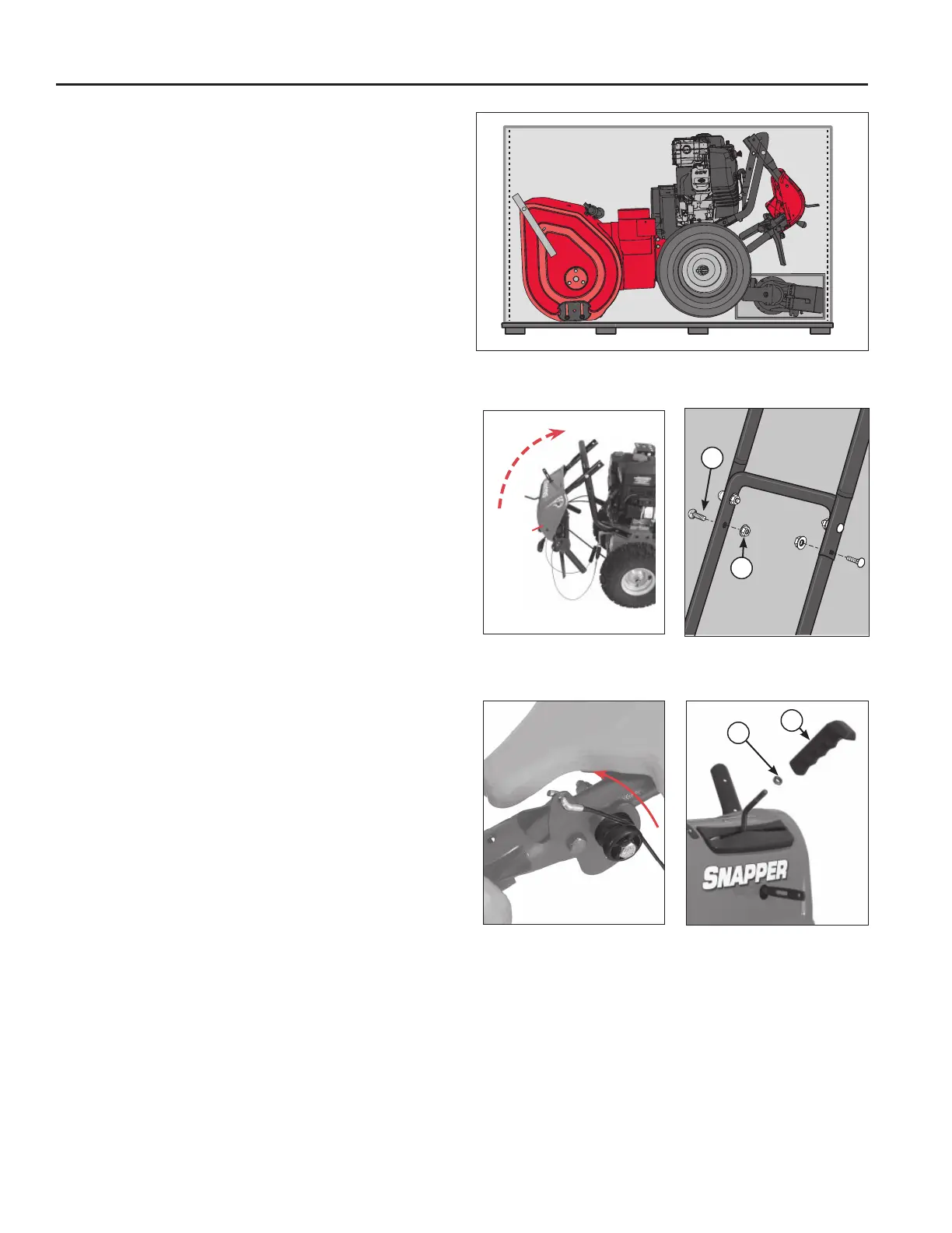
Open carton completely by cutting each corner from 1.
top to bottom as shown in Figure 3.
Open small cardboard box behind snowthrower. 2.
Remove parts bag from inside chute. Remove manu-
al packet. Ensure you have all “Items Included” prior
to assembly.
Locate the operator’s manual in the manual packet. 3.
Always read and follow the instructions in the opera-
tor’s manual. Proper care, performance tips, and
safety information are located in this important docu-
ment.
RAISE HANDLES AND CHECK
CABLES
Note: “Right” and “Left” are from the Operating
Position.
Cut orange zip ties that secure control cables to 1.
handle assembly. Be careful not to cut or damage the
control cables.
Rotate upper handle assembly (Figure 4A) up. 2.
Slide large carriage bolts (A, Figure 4B) into lower holes 3.
and fasten with flange nuts. DO NOT TIGHTEN AT
THIS TIME.
Remove shipping tape from control levers. Make 4.
sure the “Z” bend ends of the control lever cables are
secured in the holes on the control levers (Figure 5).
Make sure auger engage control and traction control 5.
cables route over the top of cable buttons as shown.
Check that all cables can move freely and are not 6.
kinked.
Tighten upper and lower nuts in handle with a 1/2” 7.
wrench or deep socket (Figure 4B).
INSTALL CHUTE ROTATOR
CONTROL HANDLE
Install thin jam nut (A, Figure 6) onto chute rotator 1.
rod. Install chute rotator control handle (B) onto chute
rotator rod turning at least 10 full clockwise rotations.
Align chute rotator control handle so it is facing for-2.
ward and use a 5/8” wrench to tighten jam nut (A)
against chute rotator control handle (B).
Slide chute rotator control handle to the right.3.
Snowthrower - Shipping Position Figure 3
Upper Handle Figure 4A
Assembly
Upper Handle Figure 4B
Assembly
Control Lever Figure 5
Cables
Jam Nut Figure 6
Installation
A
B
A
B
 Loading...