CAUTION!
When removing the DC Safety Unit cover, make sure not to damage the internal
components. SolarEdge will not be held responsible for any components
damaged as a result of incautious cover removal.
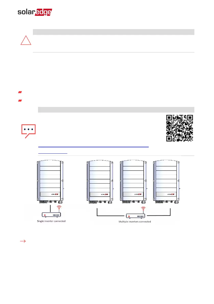
Creating an Ethernet (LAN) Connection
This communication option enables using an Ethernet connection to connect the
inverter to the monitoring platform via LAN.
Ethernet cable specifications:
Cable type – a shielded Ethernet cable (CAT6 may be used).
Maximum distance between the inverter and the router – 100 m/ 330 ft.
NOTE
If using a cable longer than 10 m / 33 ft in areas where there
is a risk of induced voltage surges by lightning, it is
recommended to use external surge protection devices.
For details refer to:
http://www.solaredge.com/files/pdfs/lightning_surge_
p
r
otection.pdf.
Example of Ethernet connection
To connect the Ethernet cable:
1. Remove the inverter cover as described
Removing the Inverter Cover
on page 49
2.
Open the communication gland #1.
Chapter 6: Setting Up Communication with the Monitoring Platform 50
Three Phase Inverter with SetApp Configuration PN: SEXXK-XXXXIXXXX
 Loading...