Backup Interface Interfaces
The following figure shows the Backup Interface interfaces for operating and
connecting to other system components.
Install cable conduits, as required by local regulations.
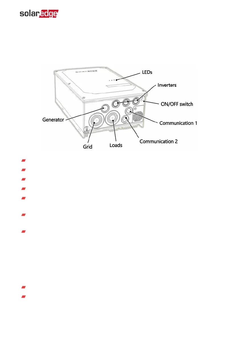
Figure 7: Backup Interface Interfaces
Inverter AC inputs - ACcables from up to three inverters.
Generator AC input - an ACcable from one external generator.
Grid ACinput - an ACcable from the grid.
Loads ACoutput - an ACcable to the loads panel.
Communication input - Communication cables from inverters and external rapid
shutdown switch.
ON/OFF switch - When ON, enables automatic transition to backup mode. When
OFF, enables manual control of the Backup Interface.
LEDs - Three LEDs (AC, Comm, Fault) indicate system performance. For more
information, see
System Performance LEDIndication
on page 25.
Connecting the Backup Interface to the Grid and AC
Loads Panel
For connecting the Backup Interface to the grid and loads panel, use the following
cable types:
For the grid - 4-4/0 AWG
For the loads panel - 4-4/0 AWG
Chapter 2: Installing and Connecting the Backup Interface 13
Backup Interface Installation Guide MAN-01-00728-1.0
 Loading...