CDX-GT40U/GT40UW/GT42UE/GT44U/GT45U/GT47UE
3
SECTION 1
SERVICE NOTE
NOTES ON HANDLING THE OPTICAL PICK-UP
BLOCK OR BASE UNIT
The laser diode in the optical pick-up block may suffer electro-
static break-down because of the potential difference generated by
the charged electrostatic load, etc. on clothing and the human body.
During repair, pay attention to electrostatic break-down and also
use the procedure in the printed matter which is included in the
repair parts.
The fl exible board is easily damaged and should be handled with
care.
NOTES ON LASER DIODE EMISSION CHECK
The laser beam on this model is concentrated so as to be focused
on the disc refl ective surface by the objective lens in the optical
pickup block. Therefore, when checking the laser diode emission,
observe from more than 30 cm away from the objective lens.
NOTE FOR REPLACEMENT OF THE SERVO BOARD
When repairing, the complete SERVO board should be replaced
since any parts in the SERVO board cannot be repaired.
NOTE FOR REPLACEMENT OF THE SENSOR BOARD
When the SENSOR board is defective, exchange the MECHANI-
CAL BLOCK (Z) ASSY 08 (Former type) or MECHANICAL
BLOCK (11CA) ASSY (New type).
Note: As for the mechanism deck (MG-101CA-188) carried in this
unit, component parts have been changed from the midway
of production. When you perform repair exchange of the
mechanism deck (MG-101CA-188), refer to “ABOUT THE
MG-101CA-188 OF FORMER AND NEW” on page 6.
CAUTION
Use of controls or adjustments or performance of procedures
other than those specifi ed herein may result in hazardous radia-
tion exposure.
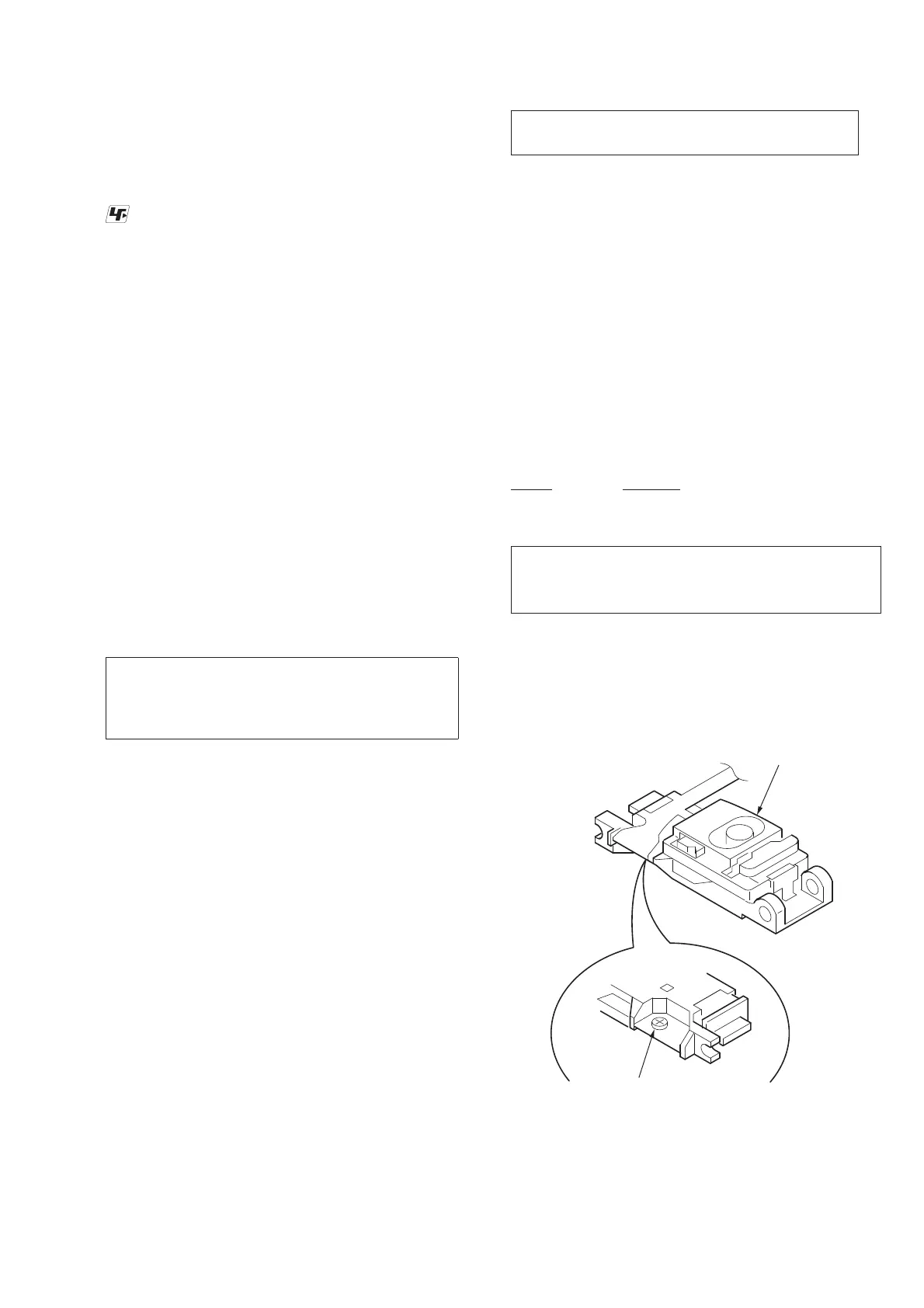
If the optical pick-up block is defective, please replace the whole
optical pick-up block.
Never turn the semi-fi xed resistor located at the side of optical
pick-up block.
TEST DISCS
Use following TEST DISC when this unit confi rms the operation
and checks it.
Part No. Description
3-702-101-01 DISC (YEDS-18), TEST (for CD)
4-225-203-01 DISC (PATD-012), TEST (for CD)
optical pick-up
semi-fixed resistor
UNLEADED SOLDER
Boards requiring use of unleaded solder are printed with the lead-
free mark (LF) indicating the solder contains no lead.
(Caution: Some printed circuit boards may not come printed with
the lead free mark due to their particular size)
: LEAD FREE MARK
Unleaded solder has the following characteristics.
• Unleaded solder melts at a temperature about 40 °C higher
than ordinary solder.
Ordinary soldering irons can be used but the iron tip has to be
applied to the solder joint for a slightly longer time.
Soldering irons using a temperature regulator should be set to
about 350 °C.
Caution: The printed pattern (copper foil) may peel away if
the heated tip is applied for too long, so be careful!
• Strong viscosity
Unleaded solder is more viscous (sticky, less prone to fl ow)
than ordinary solder so use caution not to let solder bridges
occur such as on IC pins, etc.
• Usable with ordinary solder
It is best to use only unleaded solder but unleaded solder may
also be added to ordinary solder.
Ver. 1.4
 Loading...