— 20 —
DV MECHANICAL ADJUSTMENT MANUAL VII
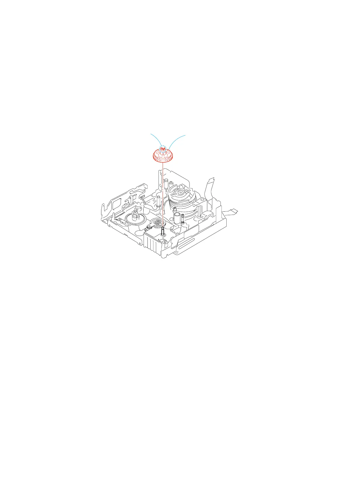
3-9. T Reel Table Assy
1. Removal procedure
1) Remove the T reel table assy 1, averting three claws A.
2. Attachment procedure
1) Confirm that the supplied part is really the T reel table assy 1.
Insert the T reel table assy 1 into the T reel shaft. Install the T
reel table assy 1 and lock it at the position where you can
hear the snapping sound. You can find the locking position by
rotating the T reel table assy 1.
1
T reel table assy
Three claws
A