— 30 —
DV MECHANICAL ADJUSTMENT MANUAL VII
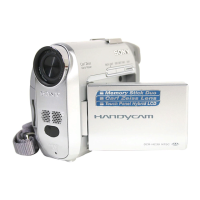
3-19.Brake (T) Block Assy
1. Removal procedure
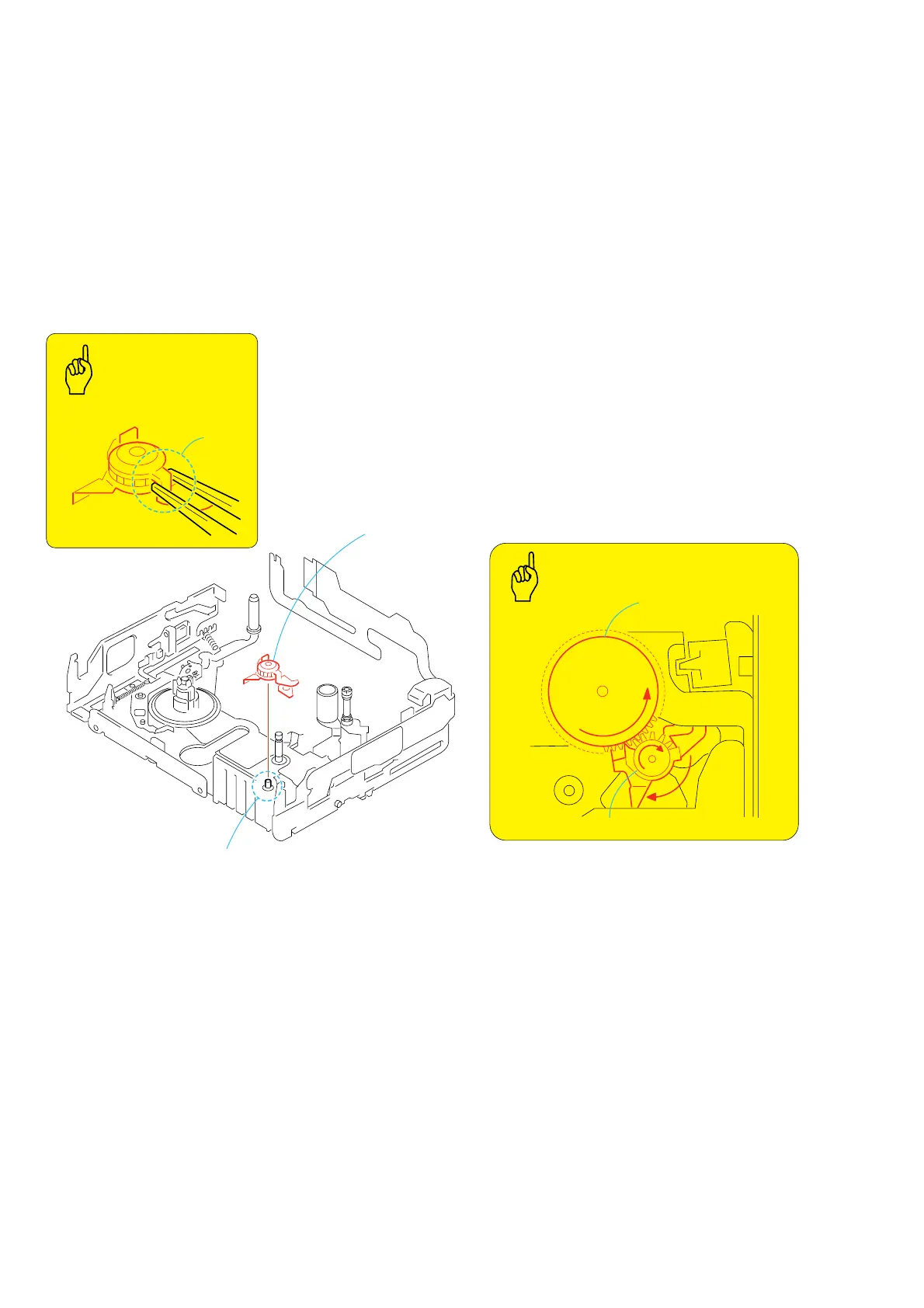
1) Hold the A portion and remove the brake (T) block assy 1.
2. Attachment procedure
1) Hold the A portion of the brake (T) block assy 1. While
inserting the slot portion into the notch of the LS chassis block
assy, install it into the shaft B.
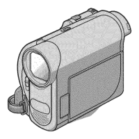
2) After completing installation of T reel table assy (Refer to 3-
9.), rotate the brake (T) block assy 1 in the clockwise direction
by rotating T reel talbe assy in the counter-clockwise direction.
(Fig. 1)
1
Brake (T) block assy
Shaft
B
T reel table assy
Brake (T) block assy
A
BRAKE (T) BLOCK ASSY
BRAKE (T) BLOCK ASSY
Points
to be noted
(Fig. 1)
Hold the
A
portion
Key Points
in Re-assembling