— 34 —
DV MECHANICAL ADJUSTMENT MANUAL VII
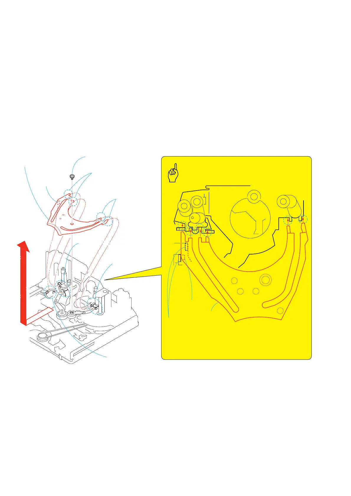
3-23.Guide Rail
1. Removal procedure
1) Remove the screw (special head screw M1.4 × 2.0) 1.
2) Remove the guide rail 2 in the direction of the arrow.
2. Attachment procedure
1) Hold the center of the guide rail 2. While pressing the TG2
cam plate assy, insert the four claws A of the guide rail in a
slant angle from the top into the drum base’s groove B. (Insert
the top tip of the rail at the same time.) Confirm at this time
that the two claws of the TG cam plate assy have entered in the
claw D of the guide rail.
2) Insert the two claws E of the T side guide rail into the groove
F of the drum base.
3) Tighten the screw (special head screw M1.4 × 2.0) 1.
Tightening torque: 0.059 ± 0.01N•m (0.6 ± 0.1kgf•cm)
GUIDE RAIL
1
Screw
(M1.4
×
2.0)
2
Guide rail
Guide rail
Two claws
C
Two claws
C
Claw
D
Claw
D
Two claws
E
S side
Drum base
T side
Four claws
A
Groove
B
Groove
F
Key Points in Re-assembling
• Confirm that the two claws
C
of the TG2 cam plate assy have
entered in the claw of the guide rail.
• Detent of the guide rail has not overridden on the groove of the
drum base.
• Guide rail must not have any twist or scars.
 Loading...