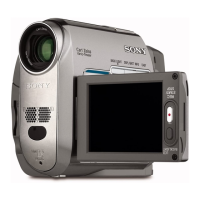
DCR-HC39E/HC41/HC42/HC42E/HC43/HC43E
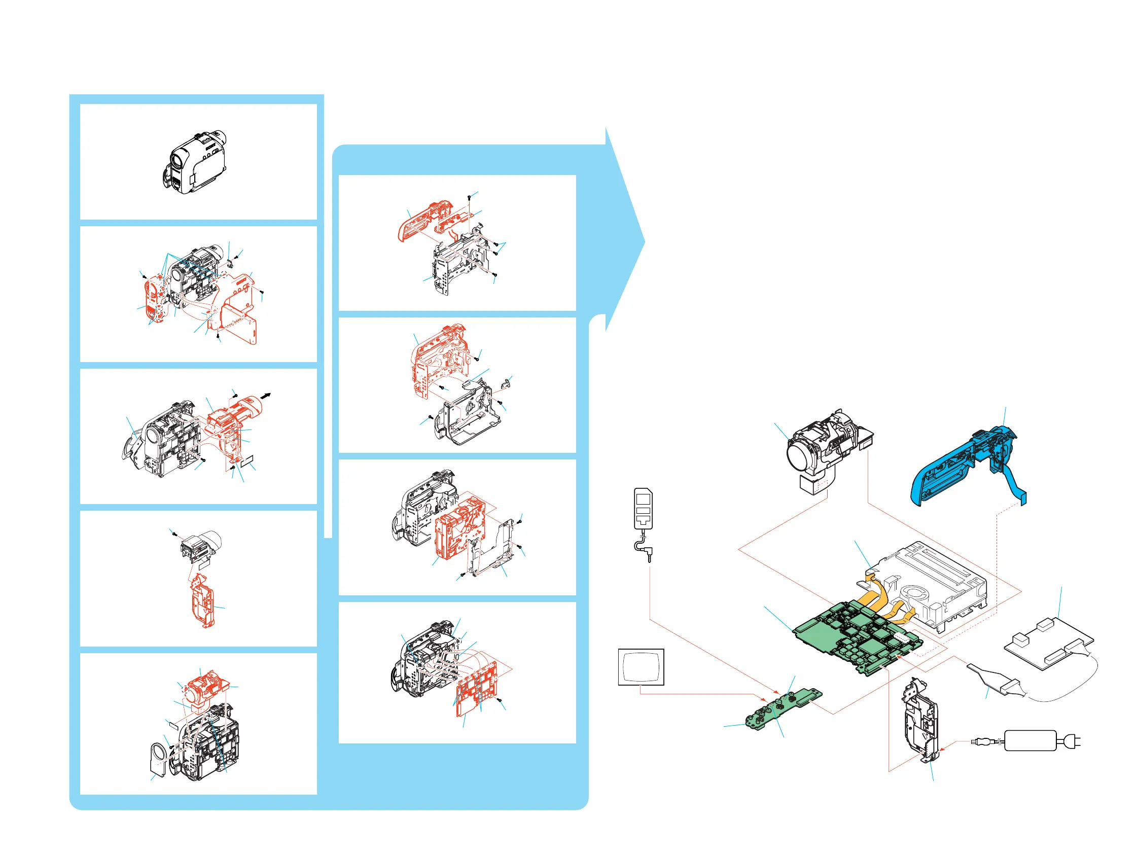
2-2. MECHANISM DECK SERVICE POSITION
2-5 2-6
1
4
4
3
3
3
9
7
8
0
5
6
2
1
5
6
6
7
2
3
4
1
1
2
3
4
2
6
7
1
4
5
3
1
2
4
6
5
3
Connection to Check the Mechanism deck
To check the mechanism deck, set the Camera or VTR to the "Forced power ON" mode.
(Or, connect the control key block (SS10300) to the CN1001 of VC-378 board and set the power switch
to the "CAMERA" or "PLAY/EDIT" position.)
Operate the VTR function using the adjustment remote commander
(with the HOLD switch set in the OFF position).
Setting the "Forced Camera Power ON" mode
1) Select page: 0, address: 01, and set data: 01.
2) Select page: A, address: 10, set data: 01
and press the PAUSE button of the
adjustment remote commander.
Setting the "Forced VTR Power ON" mode
1) Select page: 0, address: 01, and set data: 01.
2) Select page: A, address: 10, set data: 02 and
press the PAUSE button of the adjustment remote
commander.
Exiting the "Forced Power ON" mode
1) Select page: 0, address: 01, and set data: 01.
2) Select page: A, address: 10, data: 00,
and press the PAUSE button of the
adjustment remote commander.
3) Select page: 0, address: 01, and set data: 00.
1
2
Color monitor
A/V jack
LANC jack
BT panel block
JK-278 board
VC-378 board
Lens block
Mechanism deck
Control key block
(SS10300)
1
CPC-15
(J-6082-564-A)
I/F unit for LANC control
(J-6082-521-A)
8
Adjustment
remote commander
(RM95)
AC adaptor
AC IN
*: To eject a cassette, connect the cabinet (L) block assembly.
*
1
3
4
6
0
5
7
8
9
2
1
5
2
3
4
6
6
7
 Loading...