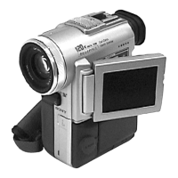
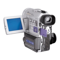
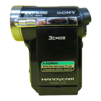
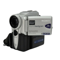
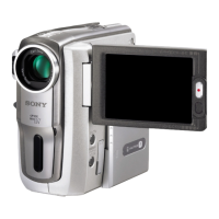
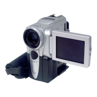
DCR-PC1000/PC1000E
2. DISASSEMBLY
2. DISASSEMBLY
2-3 2-4
E
1
2
3
D
I
D
D
D
E
3
1
2
3
2
1
3
D
H
H
4
3
2
1
5
3
9
2
1
7
8
4
5
6
4
5
6
7
8
9
4
4
2
1
HELP 02
HELP 03
7
1
3
4
5
6
J
A
HELP 06
HELP 05
2
8
9
0
Note:
Be very careful not to
damage the flexible board.
A
1
J
2
3
4
5
1
FP-220 flexible board (6P)
2
FP-168 flexible board (6P)
3
Two tapping screws (M1.7x3.5) (Black)
4
CK board assembly.
1
Two screws (M1.7x4) (Silver)
2
Tapping screw (M1.7x3.5) (Black)
3
Remove the FP-168 and FP-220 flexible board.
4
Hinge cover (R)
5
LCD panel assembly
1
Sheet (FP-220)
2
Two tape AS
3
Remove the FP-220 flexible board.
1
Two screws (M1.7x2.5) (Black)
2
Remove the control switch block(FK11800)
in the direction of the arrow .
3
Flexible board (8P)
1
Tape AS
2
FL11800 (16P)
3
Screw (M1.7x2.5) (Silver)
4
Remove the strob assembly
in the direction of the arrow .
1
CD-569 board(60P)
2
Lens flexible board (27P)
3
Tapping screws (M1.7x5) (Black)
4
Remove the lens assembly
in the direction of the arrow .
1
Screw (M1.7x2.5) (Silver)
2
Screw (M1.7x2.5) (Silver)
3
Screw (M1.7x2.5) (Silver)
4
Remove the EVF assembly
in the direction of the arrow.
5
FP-172 flexible board (80P)
6
Screw (M1.7x2.5) (Black)
7
Meter washer
8
Remove the FP-167 flexible board
in the direction of the arrow a.
9
FP-167 flexible board (24P)
1
MD flexible sheet
2
Two screws (M1.7x2.5) (Silver)
3
to
6
((27P), (10P), (10P), (29P)) of VC-398 board.
7
Control switch block (PS11800) (16P)
8
FP-166 flexible board (6P)
9
Remove the VC-398 board in the
direction of the arrow.
a
a
b
c
1
Slide the eject knob in the direction of the arrow a.
2
Open the cassette lid in the direction of the arrow b.
3
Two screws (M1.4x1.5) (silver)
4
Screw (M1.4x1.5) (silver)
5
Remove the mechanism deck, MD chassis assembly
in the direction of the arrow c.
1
Two screws (M1.7x4) (Black)
2
Two claws
3
P cabinet (C)
4
Lens flexible sheet
5
FP-168 flexible board(27P)
6
P cabinet (M) assembly
7
Two tapping screws (M1.7x3.5) (Black)
8
two claws
9
Hinge cover (C)
0
Hinge cover (M)
qa
Hinge assembly
A
V
C
-39
8
qa
Tapping screw
M1.7x3.5
3-078-890-01
F
C
Screw
M1.7x2.5
3-989-735-01
D
Screw
M1.7x4
3-084-817-31
G
Screw
M1.4x1.5
3-062-214-01
I
Screw
M1.7x4
3-087-376-01
A
Screw
M1.7x4
3-056-030-91
B
Screw
M1.7x2.5
3-084-817-11
E
Tapping screw
M1.7x5
3-080-204-21
H
Tapping screw
M1.7x3.5
3-080-204-01
J
Silver
Black
HELP 07
J
4
3
1
2
2
3
1
HELP 04
B
Screw
M1.4x2.5
3-086-368-11
Ver 1.1 2005. 05
 Loading...
