DCR-PC1000/PC1000E
3-7 3-8
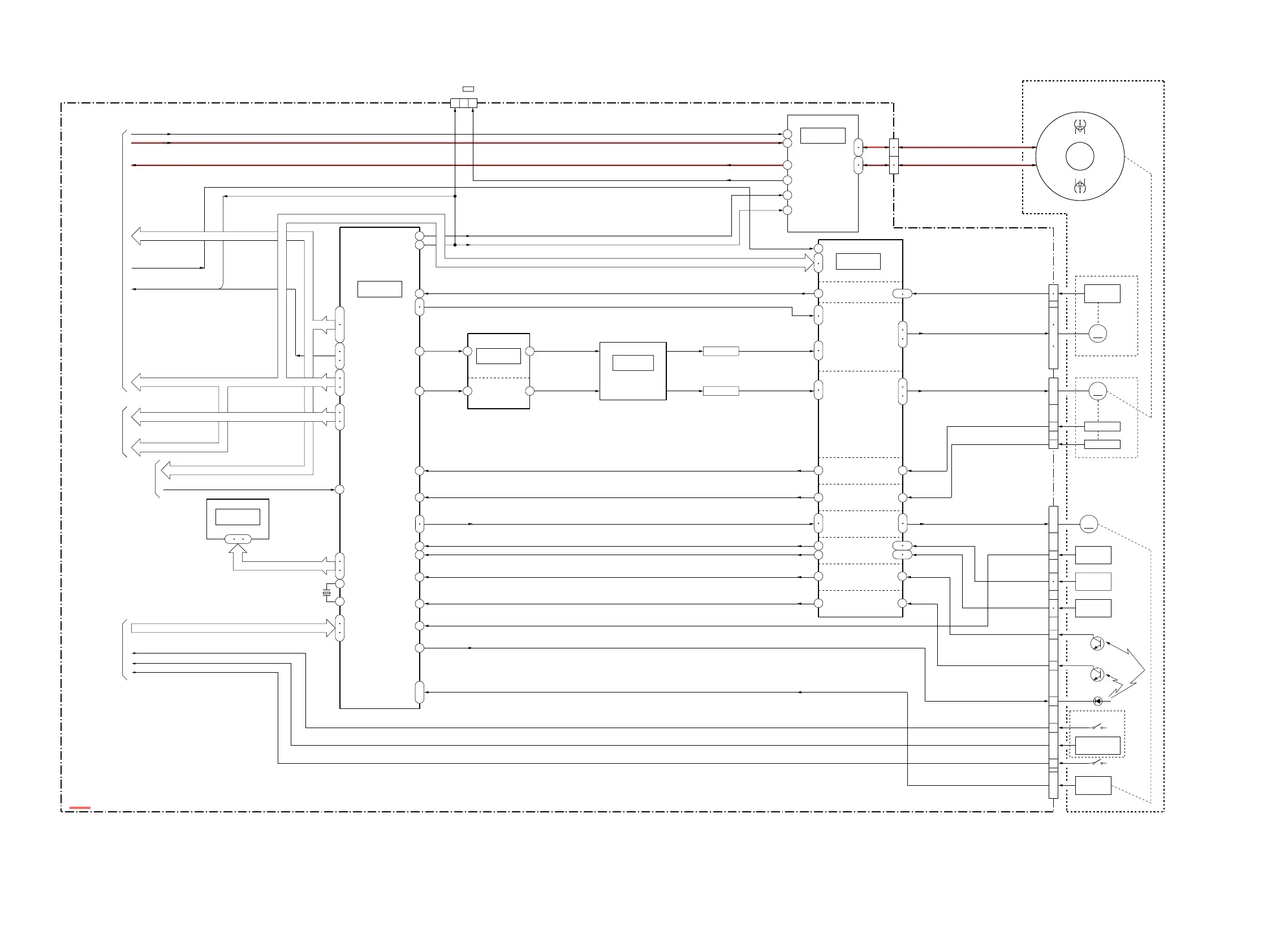
3-4. OVERALL BLOCK DIAGRAM (4/5)
( ) : Number in parenthesis ( ) indicates the division number of schematic diagram where the component is located.
X5301
20MHz
16
MODE SW A, B, C
CONTROL
SREEL FG
CAP ON,CAP FWD
DRUM PWM
FRRV
TRRT
TRRV
TAPE LED ON
13
CAP PWM
|
LOAD,UNLOAD
DRUM PG
15
DEW AD
66
63
65
36
38
1
80
77
75
67
64
33
32
72
69
63
68
65
74
78
76
23
179
178
52
33
45
CAP FG
TAPE END
TAPE TOP
106
DRUM FG
TREEL FG
MECHA
108
|
29
|
EEPROM
EEP SO,SI,SCK
SWP, FRRV, TRRT, TRRV
SWP
MC BUS
HI SO,SI,SCK
REC PROOF
CHIME SDA,CHIME SCK,CHIME VDD
XCC DOWN
CAP ERROR
DRUM ERROR
H6
J6
IC2201
PWM
G11
G8
SWITCHING
SWITCHING
Q2210
Q2211
20
SENSOR
MOTOR
N MECHA DECK
(MDX-N100)
DRUM FG AMP
S9003
9
|
LOADING
DRIVE MOTOR
H9002
H9001
C. C. DOWN
S9001
CN1008
LED9001
5
18
CONNECTOR
TAPE TOP SENSOR
Q9001
DRUM FG
CAPSTAN
MODE
22
SENSOR
11
S REEL
SWITCH
XCC DOWN
MODE SW A, B, C
S REEL +, –
T REEL +, –
LM LOARD, UNLOARD
14
MOTOR
CN1010
19
TAPE END DETECT
4PIN
T REEL
|
TAPE TOP DETECT
7
LOADING MOTOR
TAPE LED
M
REEL FG AMP
M9002
REC PROOF
S9002
9
12
SENSOR
DRUM
TAPE END SENSOR
|
20
10
6
CAPSTAN
DRUM PG
23
|
1
M
25
DRUM PG AMP
16
CAP VS
DEW
17
12
24
DRUM VS
FG
M9003
2
DRUM
Q9002
MIC9002
|
M9001
28
27
TO
OVERALL
BLOCK DIAGRAM
(5/5)
21
SWP
CN1009
FOR ADJUSTMENTS
REC/PB
CN1013
EVEN
ODD
REC CK
REC DT
TO
OVERALL
BLOCK DIAGRAM
(2/5)
(PAGE 3-4)
(PAGE 3-5)
(PAGE 3-2)
(PAGE 3-10)
VC-398 BOARD(4/5)
166
165
FG AMP
(15/23)
(15/23)
(14/23)
(14/23)
(10/23)
(23/23)
164
172
190
89
88
197
198
192
193
189
196
119
180
1
3
4
35
53 52
49
50
29
25
21
19
20
18
IC4301
44
46
RF IN
SPCK
RF IN
35
RF MON
30
RF SWP
39
SWP
38
REC CK
REC DT
RF MON
IC6001
MOTOR
DRIVE
MOTOR
DRIVE
CAPSTAN
DRIVE
IC6001
LPF
4
|
1
16
13
|
M
CN1014
IC5302
IC5301
AMP
CAPSTAN
DRUM
41
44
43
45
26 27
7 8
22 23
DEW AD
DRUM U,V,W
CAP U,V,W
FG 1,2
(1/2)
(2/2)
(2/2)
(1/2)
4
TO
OVERALL
BLOCK DIAGRAM
(3/5)
6
TO
OVERALL
BLOCK DIAGRAM
(1/5)
1
8
10
3
9
4
LPF
CPC
DIGITAL VIDEO/AUDIO SIGNAL
82
80
83
86
84
87
326
MC BUS
BS CLK
69
67
70
VD SO,SI,SCK
VSP SO, SCK
VSP SO,SI,SCK
VSP SO,SI,SCK
VSP SO,SI,SCK
20
5
3
2
6
REC PROOF
TAPE LED ON
CHIME SDA,CHIME SCK,CHIME VDD