DCR-PC1000/PC1000E
3-5 3-6
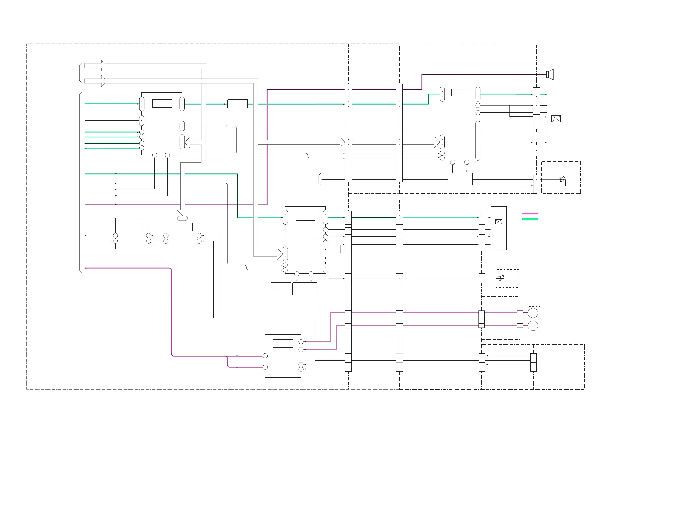
3-3. OVERALL BLOCK DIAGRAM (3/5)
( ) : Number in parenthesis ( ) indicates the division number of schematic diagram where the component is located.
PD-252 BOARD(1/2)VC-398 BOARD(3/5)
RGB
DRIVE
COM
HCK1
VR,VG,VB
COM
VST, VCK, EN, DWN, XSTBY, PCG,
HST, REF, WIDE, HCK 1/2, VP, RGT
BL ON EXTDA
BL ON EXTDA
CS
2.7 WIDE
COLOR
LCD UNIT
LCD901(1/2)
CN7505
LED901
CN7506
IC7501
37
36
35
29
7
22
23
24
TIMING
GENERATOR
2
49
46
48
CN943
CN941
PANEL R,G B
VSP SO,SI,SCK
SP+, SP–
Q4701
PANEL R
PANEL G
PANEL B
TIMING
GENERATOR
COLOR
EVF
UNIT
17
16
18
VJ-001 BOARD (2/3)
34
25
37
32
46
30
BACKLIGHT
DRIVE
R,G,B
EN, VST, REF, PCG, VCK, XSTBY,BLK,HCK1/2, HST
EVF COM CS
Q7001
MIC L
MIC R
IC7002
CN945
LCD902
CN1007
CN002 CN001
CN7501CN1015
33
24
29
31
45
37
IC7001
RGB
DRIVE
EVF R,G,B
EVF HD
EVF VD
BL H
BL L
BL -15V
25
27
29
60
59
61
45
43
41
35
22
1
37
20
10
17
16
14
11
9
MIC AMP
IC4501
B8
A1
B7
B2
SHOE MIC FR
SHOE MIC FL
SHOE MIC RR
SHOE MIC RL
FP-172 (FLEXIBLE)
(2/3)
FP-173 (FLEXIBLE)
(1/2)
FP-168 (FLEXIBLE)
(1/2)
INTELLIGENT
ACCESSORY
SHOE (1/2)
2
3
5
6
15
14
12
11
72
70
68
66
H2
G6
SP901
SPEAKER
HD
PANEL HD
HANEL VD
VD
15
5
16
15
17
AUDIO SIGNAL
VIDEO SIGNAL
64
38
20
28
PSIG
LED KC
INT MIC L
INT MIC R
27
32
IC4460
42
44
34
35
RL
RR
23 24
IC4461
3
2
12
8
A/D
CONV.
SHOE MIC I/F
23
7
4
5
3
1
24
14
11
9
2
6
6
BACK LIGHT
BACK LIGHT
DRIVE
Q7513-7516
20 34
19
21
6
52
FP-236
(FLEXIBLE)
CN001
CN944
CN946
MIC901
MIC
L
MIC
R
4
2
5
2
78
76
BACK
LIGHT
MODULE
LED902
71
69
67
65
77
75
2
1
21
23
20
22
IC4701
16:9 WIDE
PROCESS
30
28
26
34
32
7
19
44
42
40
38
36
11
10
13
22
23
3
4
13
31
26
19
18
16
5
1
2
6
9
7
26
25
24
5
4
16
17
15
27
24
26
3
4
5
28
29
BUFFER
VD SO,SI,SCK
BL CONT
TO
OVERALL
BLOCK DIAGRAM (5/5)
(PAGE 3-9)
7
VD,SO,SI,SCK
PANEL R
PANEL G
PANEL B
PANEL HD
PANEL VD
IC4401 Y OUT
IC4401 C OUT
IC4701 Y OUT
IC4701 C OUT
EVF R
EVF G
EVF B
EVF HD
EVF VD
SPCK
DSCK VM
SP+
SP–
DATA TO SFD2
SFD BCK
MIC L
MIC R
TO
OVERALL
BLOCK DIAGRAM (4/5)
(PAGE 3-7)
6
TO
OVERALL
BLOCK DIAGRAM (2/5)
(PAGE 3-4)
5
(11/23)
(13/23)
(13/23)
(18/23)
(18/23)
(17/23)
Ver 1.1 2005. 05

 Loading...