2-2
DSC-F77/FX77
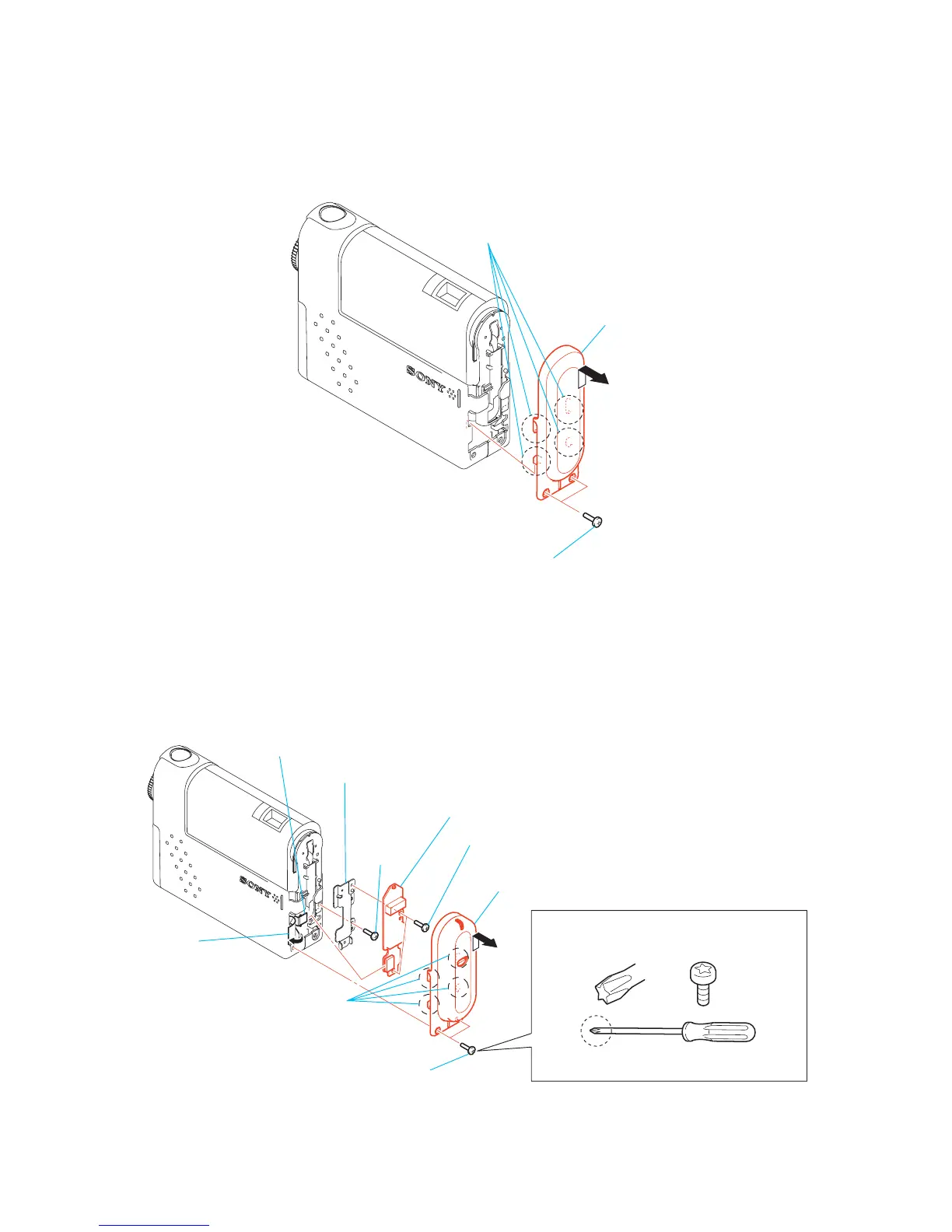
2-2. HINGE COVER, BT-14 BOARD (DSC-FX77)
2-1. HINGE COVER (DSC-F77)
Note: Follow the disassembly procedure in the numerical order given.
1 Two screws
(M1.7)
3 Hinge cover
A
2 Remove the hinge cover (BLT) assembly
in the direction of arrow A,
and releace four claws.
1 Two special BIT screws
6 Two screws (M1.7)
8 Screw
(M1.7)
9 BLT frame
7 BT-14 board
5 FP-588 flexible board
(CN1001)
4 BLT sheet
3 Hinge cover (BLT)
assembly
2 Remove the hinge cover (BLT) assembly
in the direction of arrow A,
and releace four claws.
When two SPECIAL BIT (P2 MAIN) M1.7 are
removed or installed, use ANT DRIVER
(D5LUOX113A).
ANT DRIVER
(J-2507-052-1)
Note: Be sure to use SPECIAL BIT (P2 MAIN) M1.7
(3-079-777-010) at service.
A
 Loading...