HBD-TZ210/TZ230/TZ510/TZ630/TZ710
14
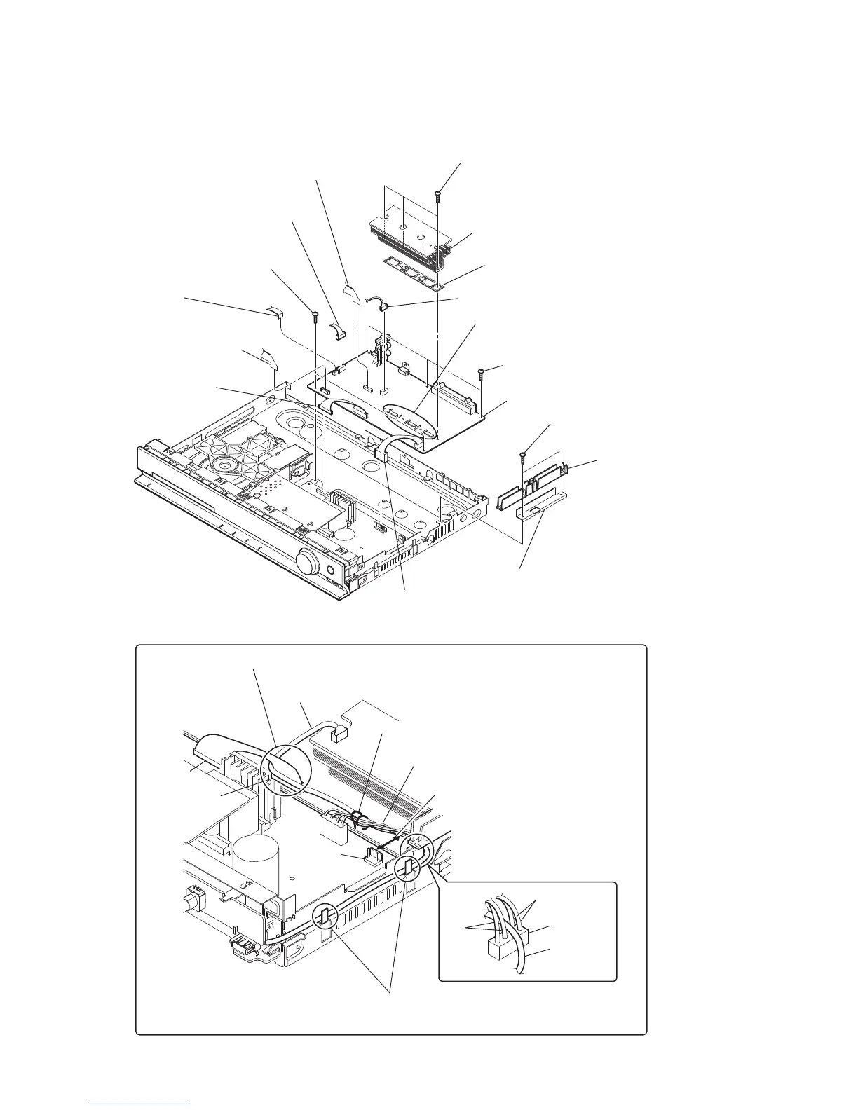
4 CN2101 (5P)
When the heat sink has been removed,
apply oil compound (G-747) to it.
6 CN1501 (6P)
8 wire (flat type) (11 core)
(CN506)
5 wire (flat type) (24 core) (CN1101)
7 wire (flat type) (5 core)
(CN1502)
9 CN906 (11P)
0 CN904 (5P)
1 two screws
(+BV3 (3-CR))
qa four screws
(+BV3 (3-CR))
qs heat sink section
qd holder (IC)
qg three screws
(+BV3 (3-CR))
qf two screws
(+BV3 (3-CR))
qh MAIN board
2 insulated plate
(POW)
3 plate shield (PC)
(TZ210: CND, AUS, EA, HK, RU, SAF/
TZ230/TZ510: CND, SAF, TW/
TZ630/TZ710: HK, CH, RU)
Arranging the USB wire
Have the USB wire spread on the inside
of the claws of the chassis.
USB wire
USB wire
CN3000
CN509
CN901
CN906
brack
red
Tie up with LP3002.
Pass the wire from CN509 over the USB wire and insert it into CN906.
Draw the USB wire through CN3000.
Keep a distance of more than 6.5 mm
between the wire and CN901.
Keep the wire tied up from lying on
the heat sink and the POWER board.
2-8. MAIN BOARD
• Abbreviation
AUS : Australian model
CH : Chinese model
CND : Canadian model
EA : Saudi Arabia model
HK : Hong Kong model
RU : Russian model
SAF : South African model
TW : Taiwan model
Ver. 1.1
 Loading...