20
HCD-GT22/GT44/GT55
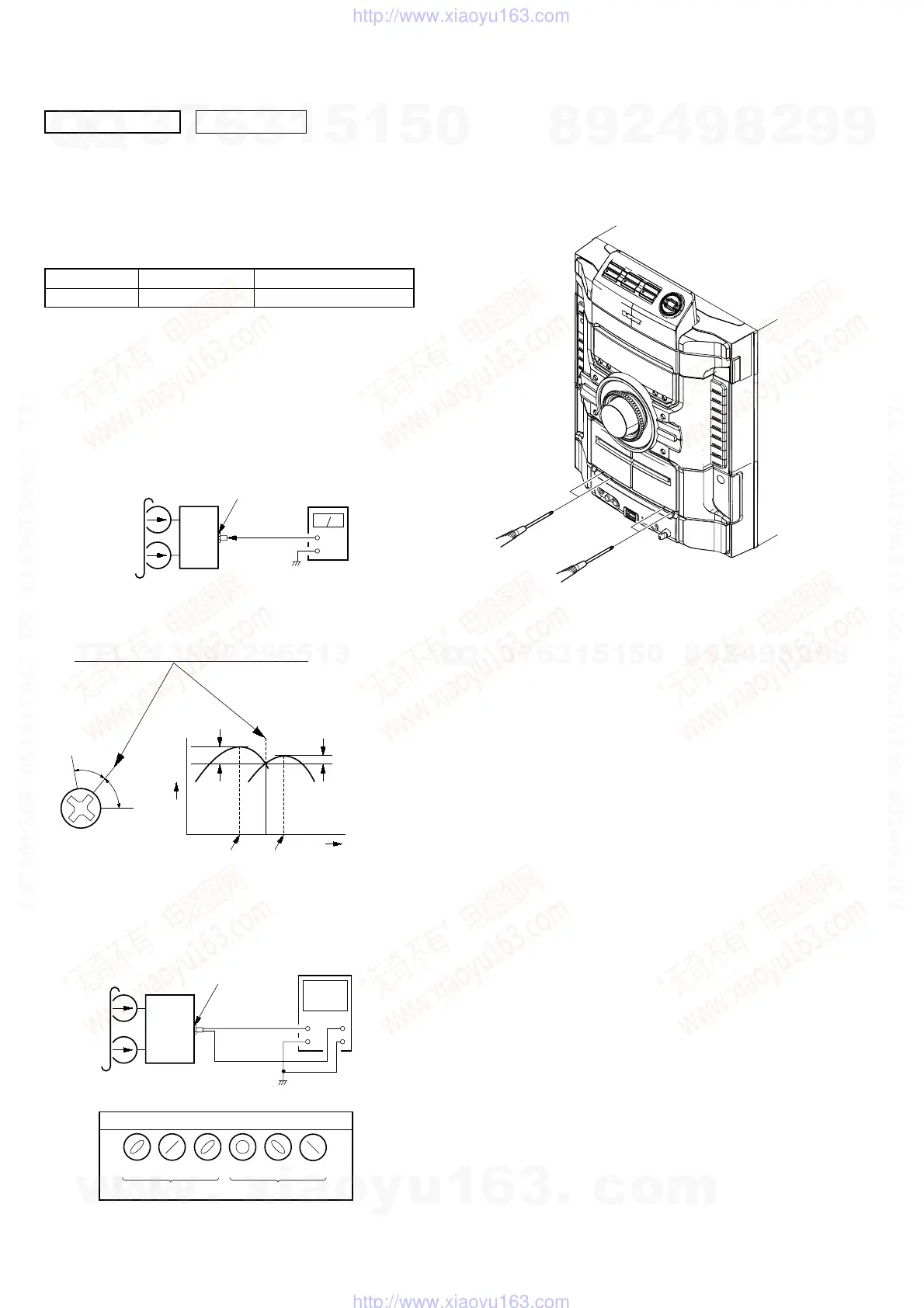
3. Mode: Playback
set
test tape
P-4-A063
(6.3 kHz, –10 dB)
oscilloscope
V
H
waveform of oscilloscope
0
°
+45
°
–45
°
+90
°
+135
°
+180
°
good
wrong
MIC board
PHONES jack
(J803)
2. Turn the adjustment screw and check output peaks. If the peaks
do not match for L-CH and R-CH, turn the adjustment screw
so that outputs match within 1dB of peak.
Screw
position
L-CH
peak
within
1dB
Output
level
L-CH
peak
R-CH
peak
within
1dB
Screw
position
R-CH
peak
SECTION 6
ELECTRICAL ADJUSTMENTS
0 dB=0.775 VDECK SECTION
set
MIC board
PHONES jack
(J803)
+
–
level mete
test tape
P-4-A063
(6.3 kHz, –10 dB)
1. Demagnetize the record/playback head with a head
demagnetizer.
2. Do not use a magnetized screwdriver for the adjustments.
3. After the adjustments, apply suitable locking compound to the
parts adjust.
TEST TAPE
RECORD/PLAYBACK HEAD AZIMUTH ADJUSTMENT
Note: Perform this adjustment for both decks.
Procedure:
1. Mode: Playback
Tape Signal Used for
P-4-A063 6.3 kHz, -10 dB Azimuth Adjustment
4. After the adjustments, apply suitable locking compound to
the pats adjusted.
Adjustment Location: Playback Head (DECK-A)
Record/Playback/Erase Head (DECK-B)
w
w
w
.
x
i
a
o
y
u
1
6
3
.
c
o
m
Q
Q
3
7
6
3
1
5
1
5
0
9
9
2
8
9
4
2
9
8
T
E
L
1
3
9
4
2
2
9
6
5
1
3
9
9
2
8
9
4
2
9
8
0
5
1
5
1
3
6
7
3
Q
Q
TEL 13942296513 QQ 376315150 892498299
TEL 13942296513 QQ 376315150 892498299
http://www.xiaoyu163.com
http://www.xiaoyu163.com
 Loading...