HCD-GTZ4/GTZ4i/GTZ5
2
1. SERVICING NOTES ............................................. 3
2. DISASSEMBLY
2-1. Disassembly Flow ........................................................... 4
2-2. Case (Side-L/R) .............................................................. 4
2-3. Top Case.......................................................................... 5
2-4. Front Panel Block ........................................................... 5
2-5. DC Fan (M101) ............................................................... 6
2-6. Back Panel ...................................................................... 6
2-7. MAIN Board ................................................................... 7
2-8. DC Fan (M102), POWER AMP Board ........................... 7
2-9. HUB Board, DMB19 Board ........................................... 8
2-10. CD Mechanism Block (CDM88B-DVBU101) ............... 8
2-11. Optical Pick-up Block (KHM-313CAB) ........................ 9
2-12. Belt (DLM3A) ................................................................ 9
3. TEST MODE ............................................................ 10
4. ELECTRICAL CHECK ......................................... 12
5. DIAGRAMS
5-1. Block Diagram - RF SERVO, USB Section - ................. 13
5-2. Block Diagram - MAIN Section - ................................... 14
5-3. Block Diagram - AMP Section - ..................................... 15
5-4. Block Diagram
- PANEL, POWER SUPPLY Section - ........................... 16
5-5. Printed Wiring Board - DMB19 Board - ........................ 18
5-6. Schematic Diagram - DMB19 Board (1/3) - .................. 19
5-7. Schematic Diagram - DMB19 Board (2/3) - .................. 20
5-8. Schematic Diagram - DMB19 Board (3/3) - .................. 21
5-9. Printed Wiring Board - MAIN Board - ........................... 22
5-10. Schematic Diagram - MAIN Board (1/3) - ..................... 23
5-11. Schematic Diagram - MAIN Board (2/3) - ..................... 24
5-12. Schematic Diagram - MAIN Board (3/3) - ..................... 25
5-13. Printed Wiring Board - HUB Board - ............................. 26
5-14. Schematic Diagram - HUB Board - ................................ 27
5-15. Printed Wiring Board - POWER AMP Board - .............. 28
5-16. Schematic Diagram - POWER AMP Board - ................. 29
5-17. Printed Wiring Board - DISPLAY Board - ..................... 30
5-18. Schematic Diagram - DISPLAY Board - ........................ 31
5-19. Printed Wiring Boards - PANEL Section - ..................... 32
5-20. Schematic Diagram - PANEL Section - .......................... 33
5-21. Printed Wiring Board - TRANS Board - ......................... 34
5-22. Schematic Diagram - TRANS Board - ........................... 35
6. EXPLODED VIEWS
6-1. Case Section .................................................................... 44
6-2. Loading Panel Section .................................................... 45
6-3. DISPLAY Board Section ................................................ 46
6-4. Front Panel Section ......................................................... 47
6-5. Back Panel Section ......................................................... 48
6-6. MAIN Board Section ...................................................... 49
6-7. Chassis Section ............................................................... 50
6-8. CD Mechanism Section (CDM88B-DVBU101) ............ 51
7. ELECTRICAL PARTS LIST .............................. 52
Accessories are given in the last of the electrical parts list.
TABLE OF CONTENTS
NOTES ON CHIP COMPONENT REPLACEMENT
• Never reuse a disconnected chip component.
• Notice that the minus side of a tantalum capacitor may be dam-
aged by heat.
FLEXIBLE CIRCUIT BOARD REPAIRING
• Keep the temperature of soldering iron around 270 °C during
repairing.
• Do not touch the soldering iron on the same conductor of the
circuit board (within 3 times).
• Be careful not to apply force on the conductor when soldering
or unsoldering.
SAFETY-RELATED COMPONENT WARNING!
COMPONENTS IDENTIFIED BY MARK 0 OR DOTTED LINE
WITH MARK 0 ON THE SCHEMATIC DIAGRAMS AND IN
THE PARTS LIST ARE CRITICAL TO SAFE OPERATION.
REPLACE THESE COMPONENTS WITH SONY PARTS
WHOSE PART NUMBERS APPEAR AS SHOWN IN THIS
MANUAL OR IN SUPPLEMENTS PUBLISHED BY SONY.
CAUTION
Use of controls or adjustments or performance of procedures
other than those specifi ed herein may result in hazardous radia-
tion exposure.
This appliance is classified as a CLASS 1
LASER product. This marking is located on
the rear exterior.
SAFETY CHECK-OUT
After correcting the original service problem, perform the follow-
ing safety check before releasing the set to the customer:
Check the antenna terminals, metal trim, “metallized” knobs,
screws, and all other exposed metal parts for AC leakage.
Check leakage as described below.
LEAKAGE TEST
The AC leakage from any exposed metal part to earth ground and
from all exposed metal parts to any exposed metal part having a
return to chassis, must not exceed 0.5 mA (500 microamperes.).
Leakage current can be measured by any one of three methods.
1. A commercial leakage tester, such as the Simpson 229 or RCA
WT-540A. Follow the manufacturers’ instructions to use these
instruments.
2. A battery-operated AC milliammeter. The Data Precision 245
digital multimeter is suitable for this job.
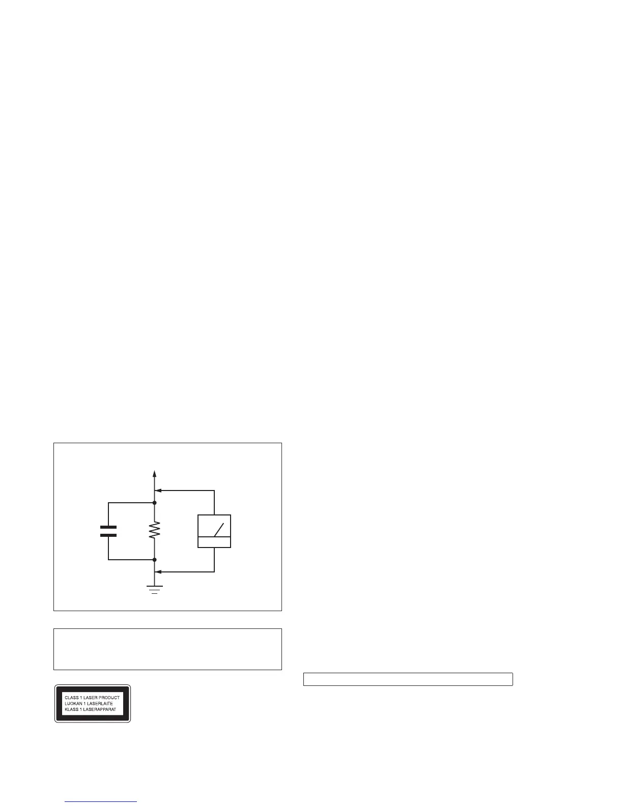
3. Measuring the voltage drop across a resistor by means of a
VOM or battery-operated AC voltmeter. The “limit” indication
is 0.75 V, so analog meters must have an accurate low-voltage
scale. The Simpson 250 and Sanwa SH-63Trd are examples
of a passive VOM that is suitable. Nearly all battery operated
digital multimeters that have a 2 V AC range are suitable. (See
Fig. A)
1.5 kΩ0.15 μF
AC
voltmeter
(0.75 V)
To Exposed Metal
Parts on Set
Earth Ground
Fig. A. Using an AC voltmeter to check AC leakage.
Ver. 1.1

 Loading...