EasyManua.ls Logo

Sony HCD-GTZ4 User Manual

Sony HCD-GTZ4
66 pages
To Next Page IconTo Next Page
To Previous Page IconTo Previous Page
Page #35 background imageLoading...
Page #35 background image
HCD-GTZ4/GTZ4i/GTZ5
HCD-GTZ4/GTZ4i/GTZ5
3535
5-22. SCHEMATIC DIAGRAM - TRANS Board -
NO804
U
BOARD
AMP
POWER
NO468
N
(3/3)
BOARD
MAIN
0.7
0.1
-32.3 -44.7
-32.9
50V
10
C909
16V
1000
C911
10k
R952
1k
R904
JW912
JW909
JW907
JW902
JW910
JW905
JW908
63V
220
C908
50V
100
C910
2SB1238-PQR-TV2
Q902
4.7k
R915
2SC3052EF-T1-LEF
Q903
JL901
JL904
JL906
JL907
JL914
JL915
JL916
JL919
JL922
JL921
JL923
JL924
JL926
1
3
4
5
6
7
8
9
2
PT902
S901
MC2837
D912
MC2837
D911
MA2J1110GLS0
D901
JW901
JW925
JW906
1
3
3P
CN901
LIVE
NEUTRAL
2NC
JL927
JL928
JL929
JL930
JL932
JL933
JL934
JL935
JL936
0
R910
0
R911
0.1
C926
JW903
C925
0.1
W019
W014
W002
W018
W004
W008
W007
W013
W005
W015
W017
W010
W003
W011
W012
W009
W006
W001
W016
JL937
JL938
JL939
JL940
JL941
JL943
JW958
C904
0.01
C903
0.01
R955
10EDB40-TB3
D908
MC2838-T112-1
D1210
10k
R957
50V
C927
3.3
MAZ8330GMLS0
D906
1
2
3
4
5
6
6P
CN908
AC-VH
AC-VL
GND
GND
AC-VL
AC-VH
1
2
3
4
5
6
7
8
9
10
11
11P
CN907
AC4
AC4
AC3
AC3
VF
VF
-VFL
DGND
EVER10
STBY RELAY
AC CUT
JL920
250V
F909
T6.3AL
250V
F908
T6.3AL
250V
F907
T1.6AL
250V
F906
T4AL
RY901
250V
F904
T6.3AL
250V
F905
T6.3AL
SUB POWER
TRANSFORMER
MAIN POWER
TRANSFORMER
TRANS BOARD
(AC IN)
(CHASSIS)
W901
SELECTOR
VOLTAGE
PT901
220V 120V230-240V
(GTZ4: E2, E51/GTZ5: E2, E51)
(GTZ4i: AUS)
(GTZ4: AR/GTZ4i/GTZ5: MX, AR)
RELAY DRIVE
-32V REGULATOR
4
B
6911
D
1035
C
F
1
E
8
A
27
NOT REPLACEABLE:
BUILT IN TRANSFORMER
0.012
C921
C920
0.012
0.012
C923
C922
0.012
(GTZ4i: US/GTZ5)
1 (GTZ5: MX)
0.82 (GTZ4i: US)
0.68 (GTZ4/GTZ4i: AEP, AUS/GTZ5: E2, E51, AR)
R955
(GTZ4: AR/GTZ4i/GTZ5: AR)
JW904
(GTZ5: MX)
GTZ4: E2, E51/
GTZ5: E2, E51, MX
GTZ4: AR/GTZ4i: US, AEP/
GTZ5: MX, AR
275V
C928
0.1
(GTZ4i: US)
(Page 29)
(Page 25)
Ver. 1.1
Question and Answer IconNeed help?

Do you have a question about the Sony HCD-GTZ4 and is the answer not in the manual?

Sony HCD-GTZ4 Specifications

General IconGeneral
BrandSony
ModelHCD-GTZ4
CategoryStereo System
LanguageEnglish

Summary

Servicing Notes

Handling Precautions

Guidelines for optical pick-up, laser diode, solder, ICs, and tray lock release.

Model Identification

Cross-reference of model numbers to their specific part numbers.

Disassembly Procedures

Disassembly Flow and Case Removal

Overview of disassembly sequence and steps for removing the unit's outer cases.

Internal Component Removal - Top, Front, Fans, Back Panel

Procedures for removing top case, front panel, DC fans, and back panel.

Internal Component Removal - Boards and Mechanism

Steps for removing main board, power amp, hub, DMB19, CD mechanism, and optical block.

Test Modes and Checks

System Diagnostic Test Modes

Panel, Common, VACS, and Cold Reset modes for system diagnostics and configuration.

Special Operational Modes and Meter Checks

Modes for tuner settings, CD shipping, tray lock, presets, VACS/meter display checks.

Electrical Performance Checks

Procedure for checking FM tuning level and signal reception.

Diagrams and Schematics

System Block Diagrams

High-level block diagrams showing functional interconnections of the system.

Printed Wiring Board Layouts

Shows the physical layout of components on various printed circuit boards.

Circuit Schematic Diagrams

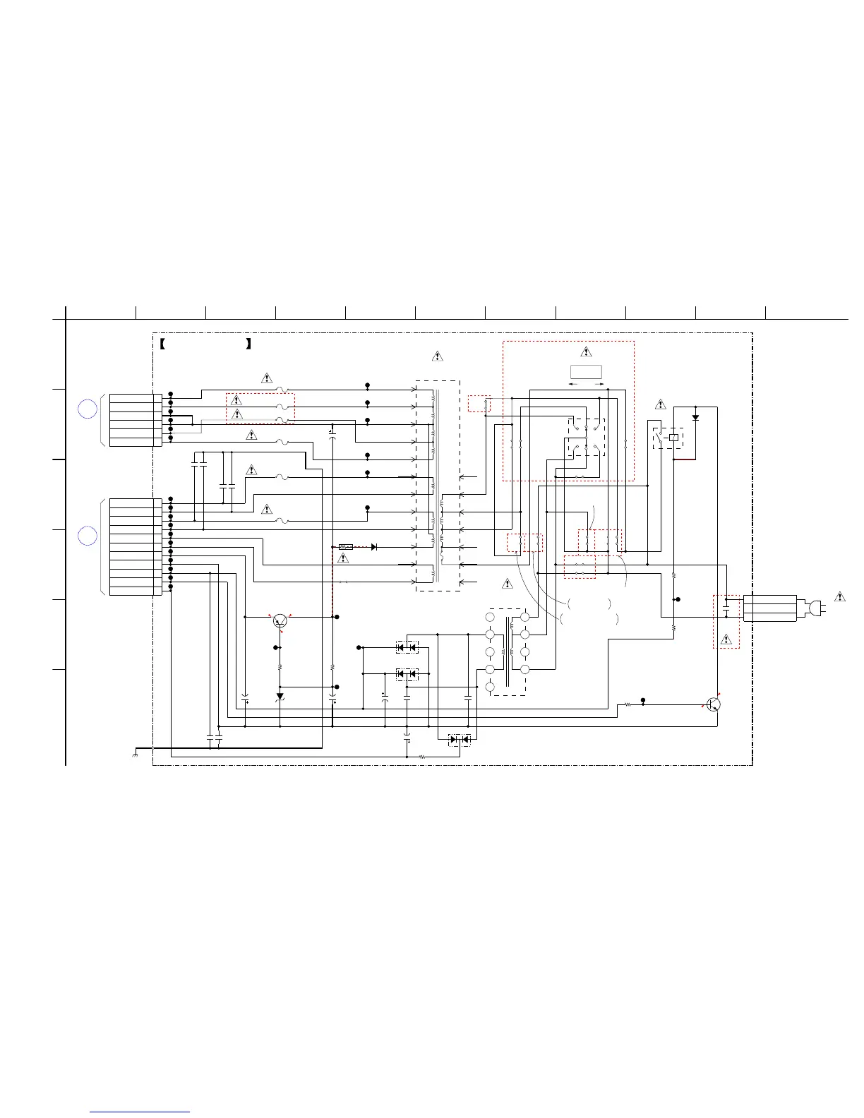
Detailed electrical schematics for all major sections and boards of the unit.

Signal Waveforms, IC Details, and Pinouts

Illustrates signal behavior, IC block diagrams, and pin function descriptions.

Exploded Views

Chassis and Panel Assemblies

Exploded views of the main case, loading panel, front panel, and back panel sections.

Internal Component Assemblies

Exploded views of the main board, chassis, and CD mechanism assemblies.

Electrical Parts List

Component Lists

Comprehensive lists of capacitors, diodes, transistors, resistors, and ICs by part number.

Revision History

Manual Version Updates

History of revisions to the service manual, including version number and date.

Related product manuals