HCD-S20
7
SECTION 2
DISASSEMBLY
• This set can be disassembled in the order shown below.
2-1. DISASSEMBLY FLOW
Note: Follow the disassembly procedure in the numerical order given.
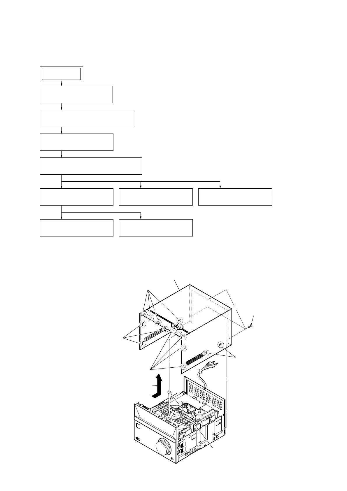
2-2. TOP COVER ASSY S20
2-2. TOP COVER ASSY S20
(Page 7)
SET
2-3. POWER CORD (AC1), REAR PANEL
(Page 8)
2-4. CD DOOR (S20)
(Page 8)
2-6. FRONT PANEL BLOCK
(Page 9)
2-9. MAIN BOARD
(Page 11)
2-7. VFD BOARD
(Page 10)
2-8. USB BOARD
(Page 10)
2-10. POWER BOARD
(Page 11)
2-5. LOADER (TDL-5) & OPU ASSY (CDM1)
(Page 9)
1 three screws (2)
2 Remove the top cover assy S20
in the direction of an arrow.
5 top cover assy S20
3 four claws
4 connector
(XP1)
3 four claws
3 two claws
3 three claws

 Loading...