HCD-S20
9
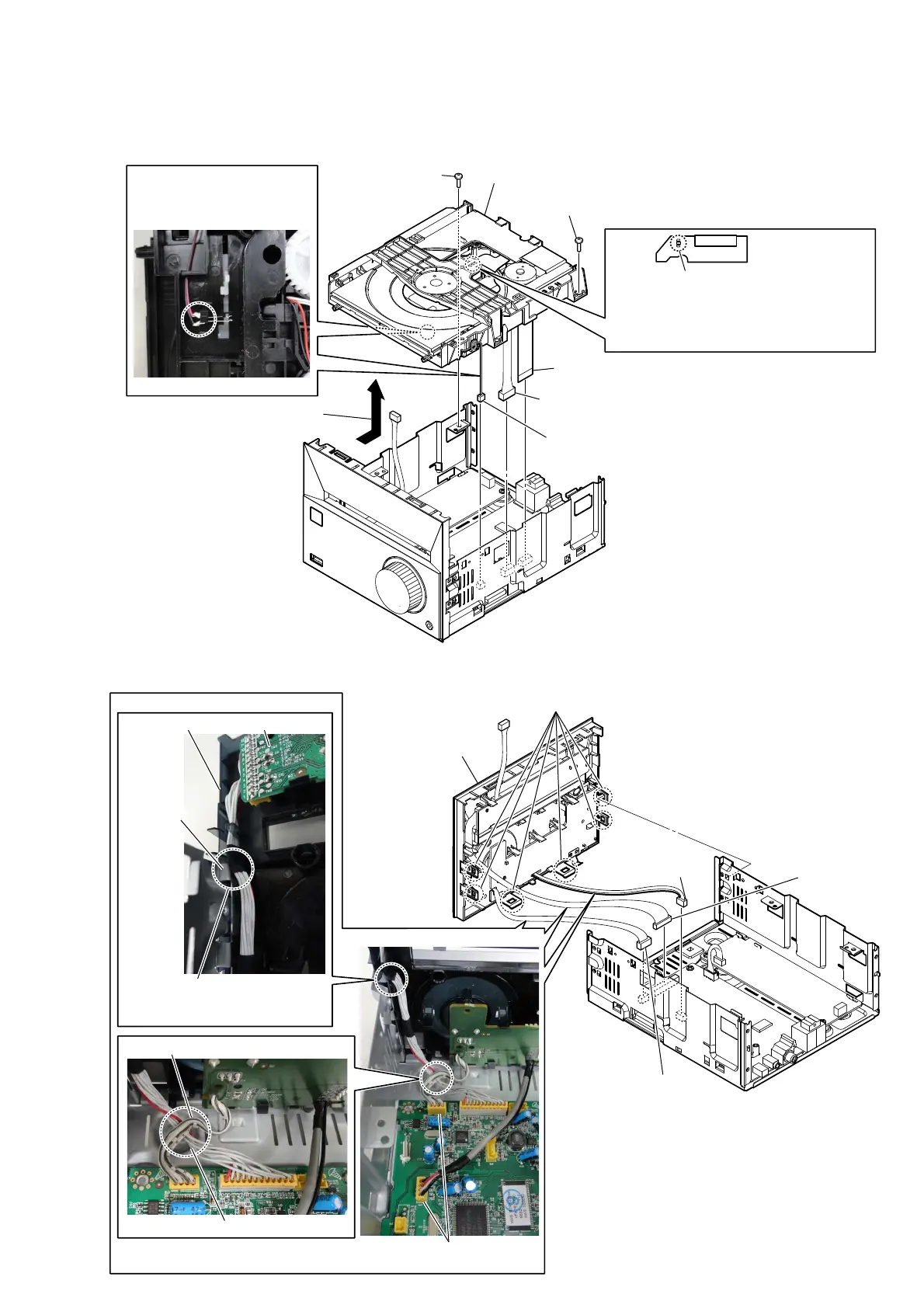
2-5. LOADER (TDL-5) & OPU ASSY (CDM1)
1
Solder the short-land.
Note 2: When assembling the loader (TDL-5) &
OPU assy (CDM1), remove the solder of
short-land after connecting all flexible flat
cable and connector.
2 screws (3)
2 screws (3)
5 connector
(XP3)
4 flexible flat cable
(XP2)
7
loader (TDL-5) & OPU assy
(CDM1)
3
Remove the loader (TDL-5) & OPU
assy in the direction of an arrow.
6
connector (XP4)
Note 3:
Since the wire is very thin, it is easy to cut.
When disconnecting, do it while holding the
connector part.
.
Note 1:
Before disconnecting the flexible flat cable of
the loader (TDL-5) & OPU assy (CDM1)
, solder the short-land.
– Bottom view –
Note 4: The wire is soldered to the
terminal of the switch.
Be careful so that not cut
or bend the terminal.
2-6. FRONT PANEL BLOCK
4 six claws
5
front panel block
– Rear right view –
3 connector
(XP12)
1 connector
(XP6)
2 connector
(XP9)
Wire setting
Wire from USB board is upper.
Wire from VFD board is lower.
– Rear view –
Note 2:
These connectors have the same number of pins.
When connecting, be careful not to mistake.
VFD board
chassis
front panel block
Note 1:
When installing the front panel
block, be careful not to bite the
wire at the chassis.

 Loading...