HCD-SBT100/SBT100B/SBT300W/SBT300WB
16
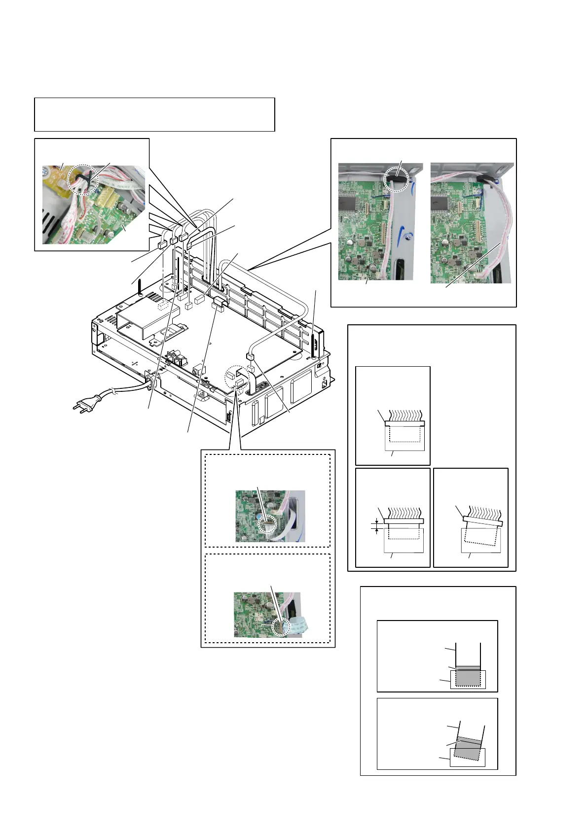
2-12. CHASSIS (MAIN) BLOCK-1
OK
NG
8 flexible flat cable (9P)
(CN251)
8 flexible flat cable (9P)
(CN104)
2 flexible flat cable (5P)
(CN502)
CN507
7 connector
(CN304)
4 connector
(CN3002)
5 connector
(CN905)
3 connector
(CN831)
coating clip
MAIN board
WireVeWWiQJ
Note 3:
Wire must not be extends
from the edge of the chassis.
WireVeWWiQJ
lead pin
MAIN
board
RELAY board
6 Remove the
wire from the
coating clip.
1 Remove wires from
the lead pin.
–5eDrYieZ–
Note 4:
When you install the connector, please
install them correctly.
There is a possibility that this machine
damages when not correctly installing it.
Insert is shallow
Insert is straight
to the interior.
connector
Insert is incline
connector
connector
connector
connector connector
NG
OK
NG
(SBT100B/SBT300WB)
(SBT100/SBT300W)
Note 5:
When installing the flexible flat cable,
ensure the colored line.
No slanting after insertion.
colored line
colored line
Inserting is straight to the interior.
Inserting is slant.
flexible flat cable
flexible flat cable
connector
connector
OK
NG
Note 1:
CN3002 and CN507 are quantity of pins of the same.
Do not insert to the wrong connector absolutely.
There is a possibility that the unit may be damaged if the wrong.
Note 2:
Do not remove this connector (CN501)
at this point.
It is necessary to process electrostatic
measures of optical pick-up.
 Loading...