HCD-SBT100/SBT100B/SBT300W/SBT300WB
19
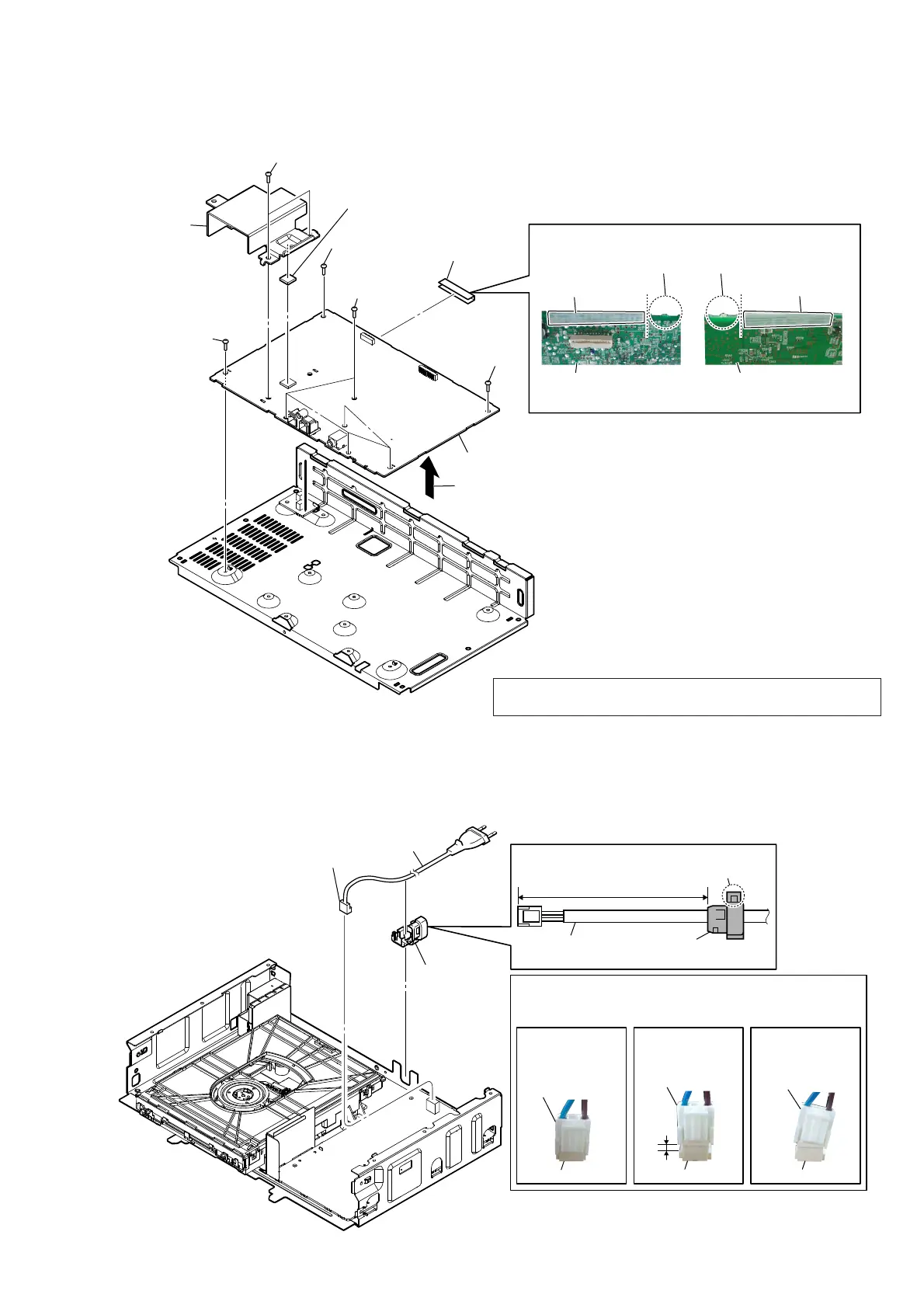
2-16. MAIN BOARD
2-17. POWER CORD (AC1)
4 screw
(BVTP3 u 8)
4 screw
(BVTP3 u 8)
3 radiation sheet
4 screw
(BVTP3 u 8)
7 MAIN board
MAIN board
ditch
4 five screws
(BVTP3 u 8)
1 two screws
(BVTP3 u 8)
2 heatsink
(AMP)
6 tape
(sub material)
tape
(sub material)
– Top view –– Bottom view –
– Rear view –
Tape VXE materiaO VettiQJ
MAIN board
ditch
tape
(sub material)
5 Remove the MAIN board block
in the direction of an arrow.
70 to 75 mm
3 power cord
(AC1)
2 cord bush
(2104)
power cord
claw
cord bush
(2104)
&RUGEXVKVHWWLQJ
1 power cord connector
(CN901)
Insert is shallow
Insert is straight
to the interior.
Insert is incline
connector
connector
connector
connector
NGOK NG
connector
connector
Note:
When you install the connector, please install them correctly.
There is a possibility that this machine damages when not
correctly installing it.
Note: When the complete MAIN board is replaced, refer to “CHECKING
METHOD OF NETWORK CONNECTION” on page 5.
 Loading...