HXR-NX70C/NX70E/NX70J/NX70N/NX70P/NX70U
2-11
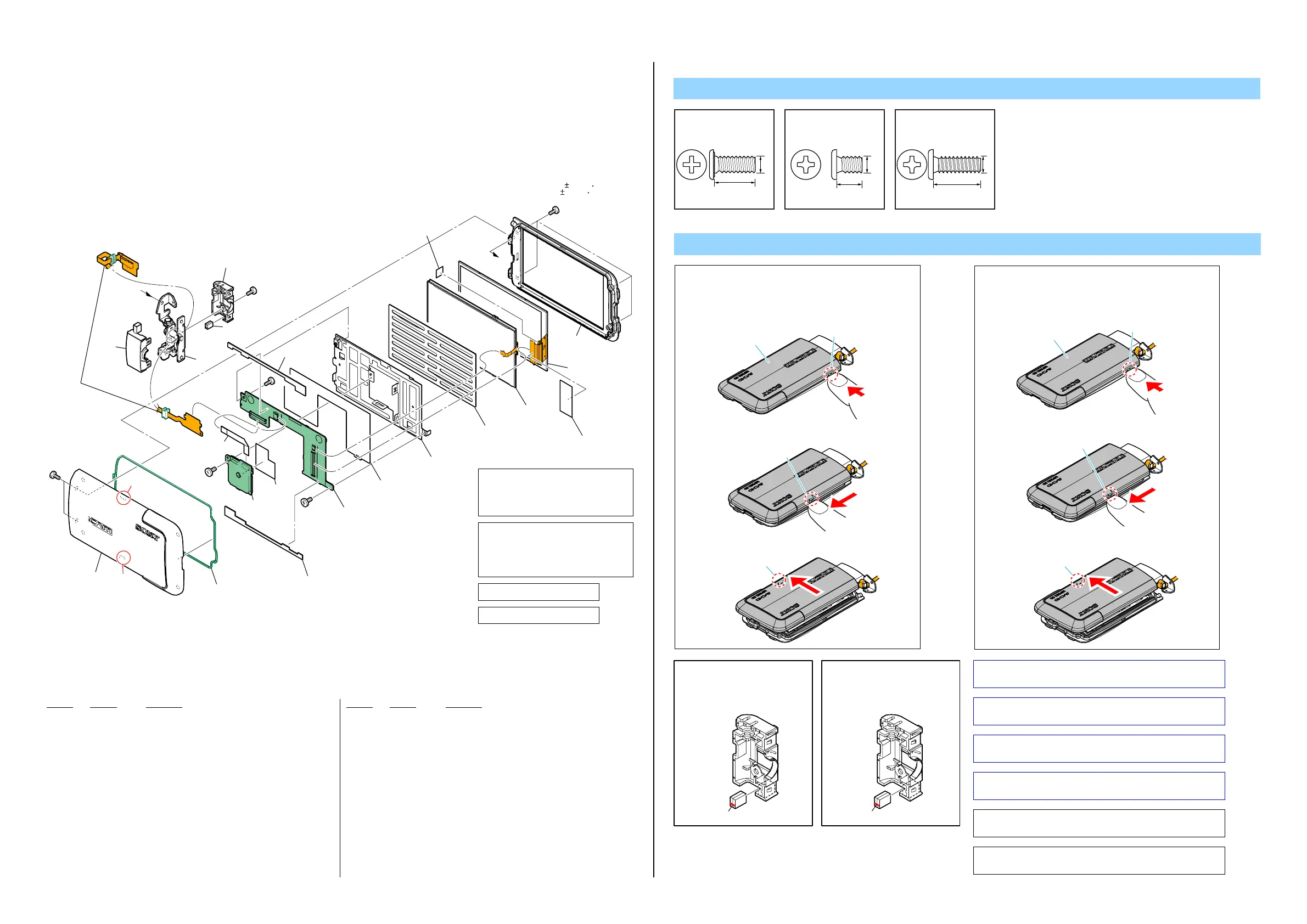
2-1-9. LCD SECTION
Note
Screw
Note 2: Refer to "Assembly-10: The Method of attachment of
FP-1380 Flexible Board.".
Note 2:
“Assembly-10: The Method of attachment of FP-1380
Flexible Board.”を参照してください。
Note 3: Refer to "Assembly-11: Installation Cautions of the
LCD Block.".
Note 3:
“Assembly-11: Installation Cautions of the LCD
Block.” を参照してください。
Note 5: Cut SHEET, LIGHT INTERCEPTION (3-089-986-01)
into the desired length and use it.
Note 5:
SHEET, LIGHT INTERCEPTION (3-089-986-01) は
指定のサイズに切って使用すること。
Note 4:
指の爪か、キャビネットに傷を付けない程度にやわら
かい板状のものをAの箇所に差し込む。
P Cabinet (C) Assyの爪を折らないために、以下の手順で
P Cabinet (C) Assyを取り外してください。
1
差し込んだものを矢印方向にスライドさせて、爪1箇所
を外す。
2
P Cabinet (C) Assyを矢印方向にスライドさせて爪1箇所
を外し、P Cabinet (C) Assyを取り外す。
3
Claw
A
Claw
P Cabinet (C) Assy
401 X-2581-413-1 CABINET (C) ASSY, P (Note 4)
402 4-282-267-01 PACKING, P CABINET
403 4-283-324-01 SHEET, PANEL FIXED
404 A-1808-076-A GP392ASSY (NX70E/NX70J/NX70N/NX70P/NX70U)
405 1-838-558-21 CABLE, FLEXIBLE FLAT (FFC-254)
(NX70E/NX70J/NX70N/NX70P/NX70U)
406 4-283-285-01 SHEET, GP (NX70E/NX70J/NX70N/NX70P/NX70U)
407 A-1825-459-A PD-438 BOARD, COMPLETE
408 4-283-278-01 INSULATING SHEET
409 4-282-373-01 FRAME, LCD
410 4-283-280-01 CUSHION (91000), LCD
411 4-285-676-01 TAPE (A (P))
412 A-1833-642-A CABINET (M) ASSY (SERVICE), P
Ref. No. Part No. DescriptionRef. No. Part No. Description
413 1-883-175-11 FP-1380 FLEXIBLE BOARD (Note 2)
414 4-282-311-01 COVER (O), HINGE
415 X-2581-425-1 HINGE ASSY, LCD
416 1-471-504-11 MAGNET (ND5X3.5X2.4-B) (Note 1)
417 4-282-312-01 COVER (U), HINGE
418 3-089-986-01 SHEET, LIGHT INTERCEPTION (Note 5)
LCD901 1-811-403-11 LCD WITH TOUCH PANEL (Note 3)
LED901 1-487-270-11 BLOCK, LIGHT GUIDE PLATE (3.5) (Note 3)
#2 2-635-562-31 SCREW (M1.7)
#3 2-660-401-01 SCREW (M1.7), NEW TRU-STAR, P2
#12 3-080-204-21 SCREW, TAPPING, P2
#3
LCD901
(Note 3)
LED901
(Note 3)
#2
#12
#2
#3
#2
401
(Note 4)
402
A
A
403
403
404
406
405
413
(Note 2)
407
408
409
410
417
416
(Note 1)
418
(Size: 5.0mm X 5.0mm)
(Note 5)
411
412
415
414
(Claw)
(Claw)
(0.13 0.02N m
(1.3 0.2kgf cm))
図中で取り外しているねじで、トルク
の記載が無いねじは、下記のトルクで
締めつけてください。
(0.13±0.02N・m (1.3±0.2kgf・cm))
Tighten screws that are removed
without specified torque in the figure
below to the following torque.
(0.13±0.02N・m (1.3±0.2kgf・cm))
緑色の部品はパッキンです。
Green parts are packings.
#2: M1.7 X 4.0
(Black)
2-635-562-31
4.0
1.7
#3: M1.7 X 2.5
(Red)
2-660-401-01
2.5
1.7
#12: M1.7 X 5.0 (Tapping)
(Black)
3-080-204-21
1.7
5.0
Note 1:
Put the marking side
together on the position
of figure when
you install the magnet.
Marking
Note 1:
マグネットを取付ける
際は,マ−キング面を
図の位置にあわせて
ください。
マーキング
Note 4:
1
2
3
Remove the P Cabinet (C) Assy using the
following procedure so as not to damage
the claws of the P Cabinet (C) Assy.
Insert your finger nail or a plate that will not scratch
the cabinet into slit A.
Slide the finger nail or the plate in the arrow direction
to release the claw.
Slide the P Cabinet (C) Assy in the arrow direction to
release the claw, and detach the P Cabinet (C) Assy.
Claw
A
Claw
P Cabinet (C) Assy
 Loading...