HXR-NX70C/NX70E/NX70J/NX70N/NX70P/NX70U
2-7
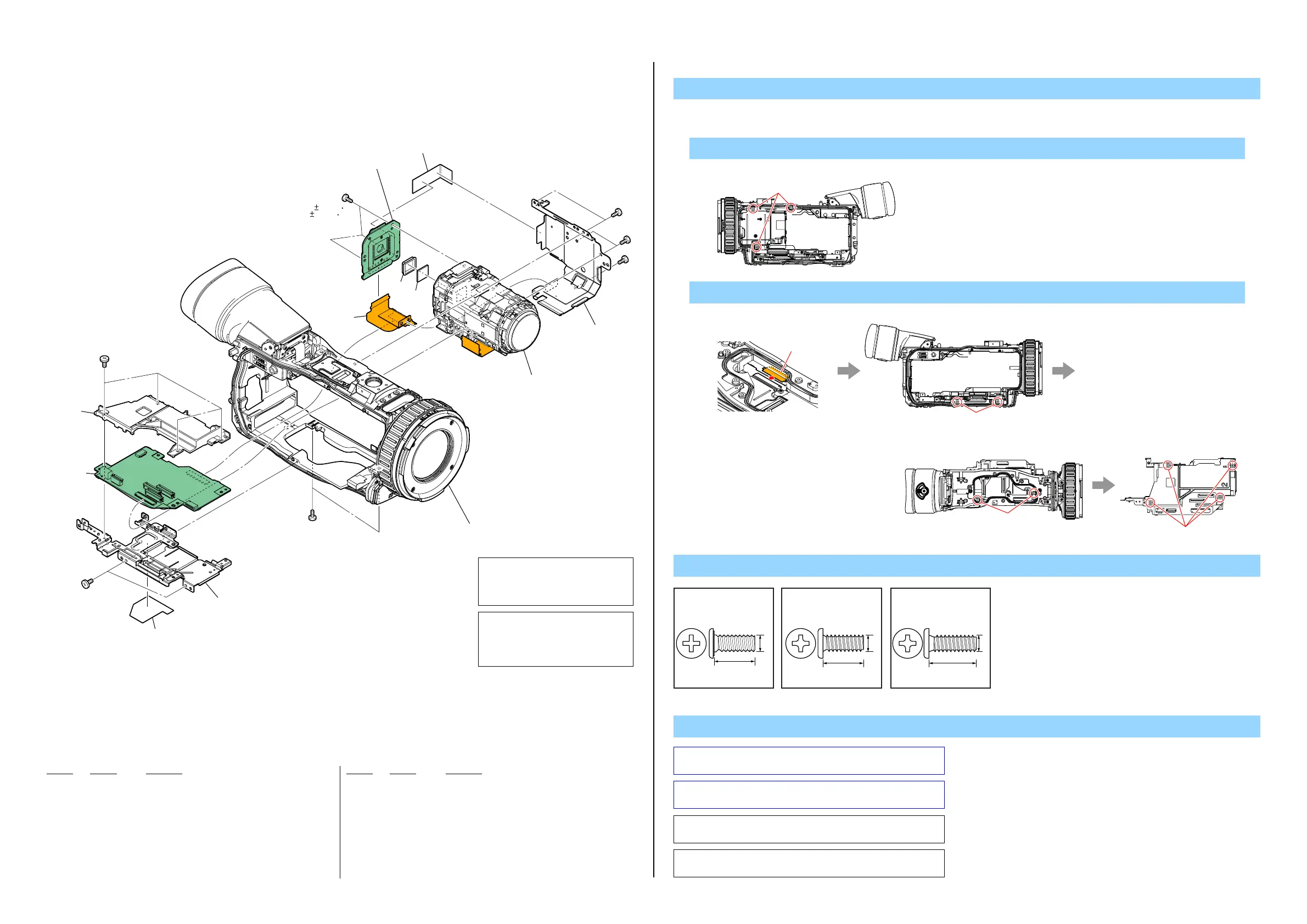
2-1-5. LENS SECTION
ns: not supplied
1. Remove to numerical order (1 to 2) in the left figure.
DISASSEMBLY
1 #2 X 3
Right View
#2
Screw
VC-633
#2
1 205
210
209
211
(Note 2)
Chassis Section-2
(See page 2-8)
#2
#2
#12
#11
#2
#2
2 203
206
207
204
202
201
208
(including CM-121 complete board,
IC6701 (CMOS imager))
(Note 1)
(0.12 0.02N m
(1.2 0.2kgf cm))
2 #2 X 8
Left ViewBottom View
#2
Disconnect
flexible board
#2
#2
Bottom View
Top Vi ew
Note
Note 1: Be sure to read “Precautions for Replacement of Imager”
on page 6-1 when changing the imager.
Note 1:
イメージャの交換時は6-1ページ、“イメージャ交換時の
注意”を必ずお読みください。
Ref. No. Part No. Description
Ref. No. Part No. Description
201 4-283-273-01 SHEET, HD PROTECTION
202 X-2581-421-1 FRAME (VC) ASSY
203 A-1825-510-A VC-633 BOARD, COMPLETE (SERVICE)
204 4-282-273-01 GUARD, VC
205 A-1733-302-A DEVICE, LENS LSV-1390A (SERVICE)
206 1-883-172-11 FP-1377 FLEXIBLE BOARD
207 1-856-033-21 OPTICAL FILTERBLOCK (OFB-03-52)
208 3-216-044-01 RUBBER (1270), SEAL
209 A-1785-655-A CMOS BLOCK ASSY (including CM-121 complete board,
IC6701 (CMOS imager)) (Note 1)
210 4-282-364-01 FRAME (R), LENS
211 4-283-270-01 SHEET, CM RADIATION (Note 2)
#2 2-635-562-31 SCREW (M1.7)
#11 3-078-890-11 SCREW, TAPPING
#12 3-080-204-21 SCREW, TAPPING, P2
図中で取り外しているねじで、トルク
の記載が無いねじは、下記のトルクで
締めつけてください。
(0.13±0.02N・m (1.3±0.2kgf・cm))
Tighten screws that are removed
without specified torque in the figure
below to the following torque.
(0.13±0.02N・m (1.3±0.2kgf・cm))
#2: M1.7 X 4.0
(Black)
2-635-562-31
4.0
1.7
#11: M1.7 X 4.0 (Tapping)
(Silver)
3-078-890-11
4.0
1.7
Note 2: The CM Radiation Sheet when peeling off once, so that it
cannot be reused.
Note 2:
CM Radiation Sheetは一度剥がすと粘着力が弱くなるた
め、再利用はしないでください。
#12: M1.7 X 5.0 (Tapping)
(Black)
3-080-204-21
1.7
5.0
 Loading...